
619 – GUGGENHEIM HELSINKI MUSEUM
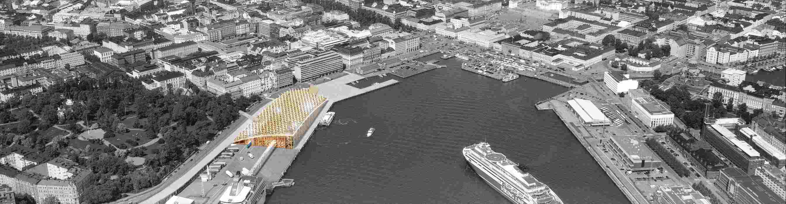
Laivasillankatu, Port of Helsinki, Finland.
60°9’36,04”N / 24°57’19,07”E
Museum: 14,941 sqm; Makasiini Terminal: 1,000 sqm; Shops/Public services: 620 sqm; Footbridge to park: 270 sqm; 2014 – ; (01/619).
- Environment
- Landscaping
- Town planning
- Architecture
- Interior architecture
- Structure
- MEP engineering
- Project economy
- High environmental quality and energy concepts
- Project management
- Cost management
- Overall coordination
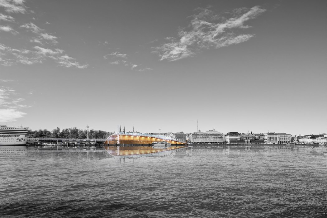
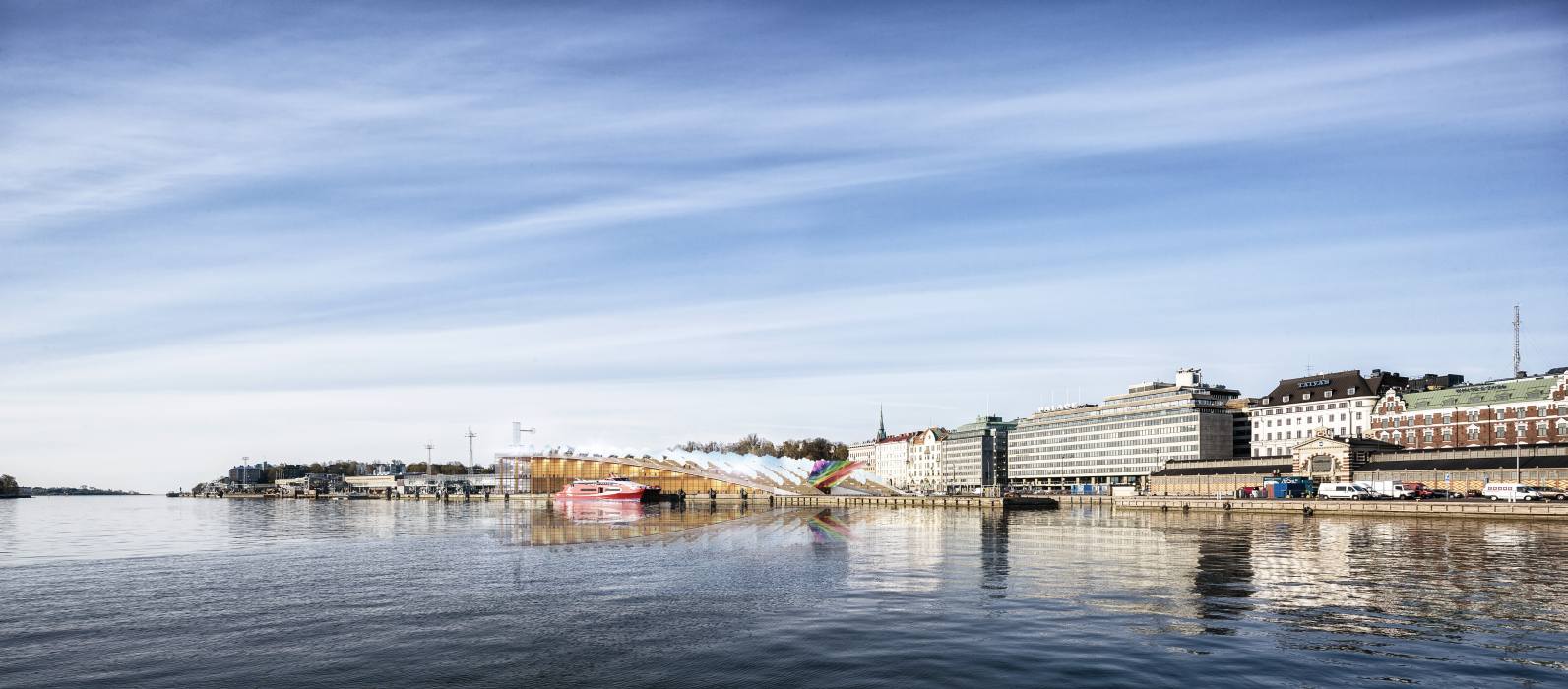
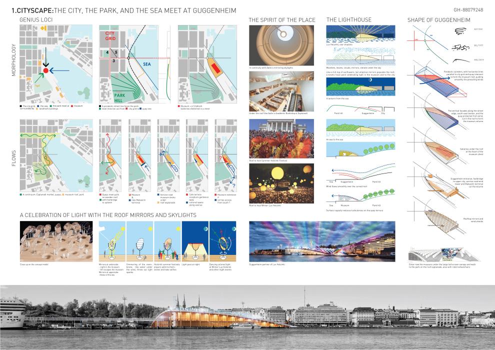
A new place to live in the city
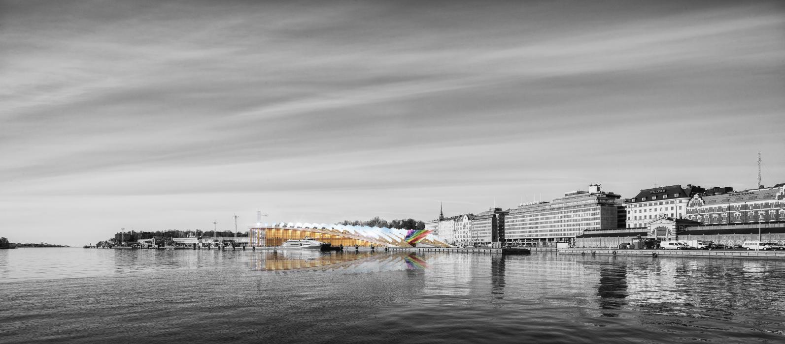
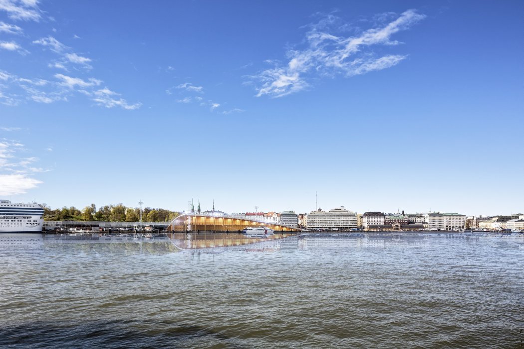
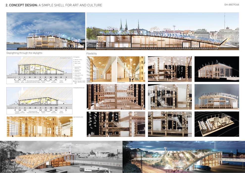
The new museum is located at the focal point of the façade of Helsinki looking at its haven (an eye to the sea and a lantern from the sea), the ideal location for a place where people may meet each other and interact with the Four Elements and the City through contemporary Art, Design and Architecture.
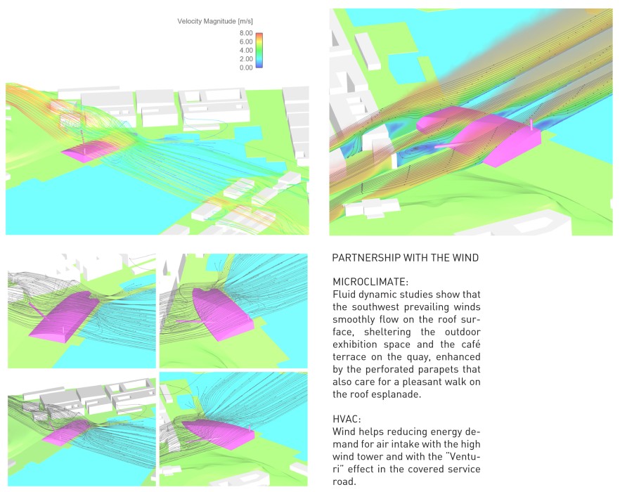
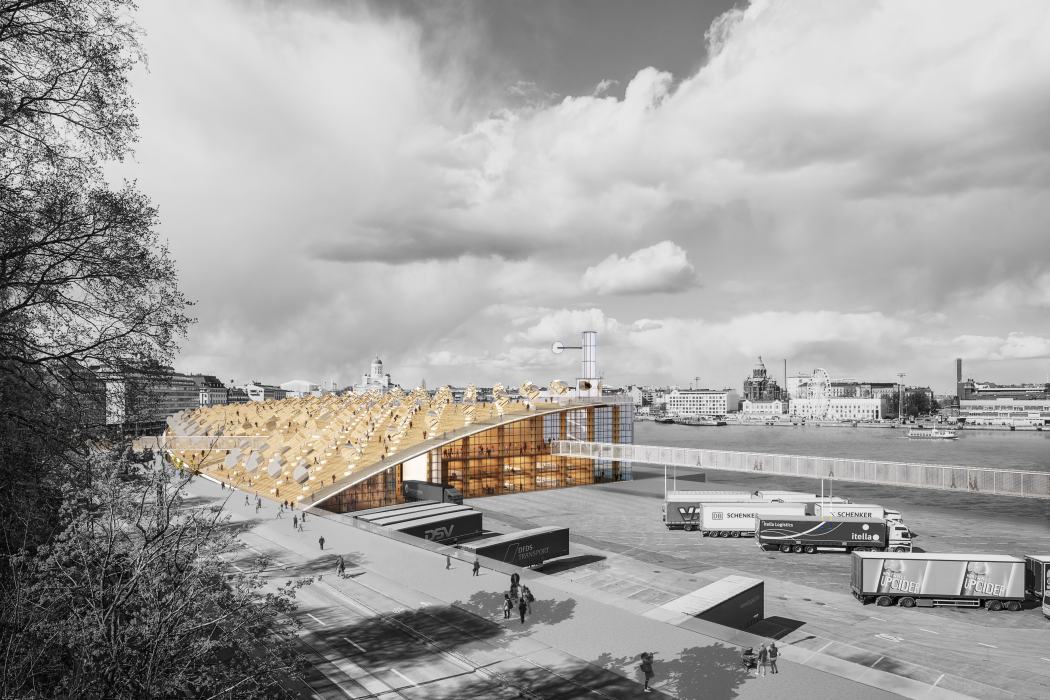
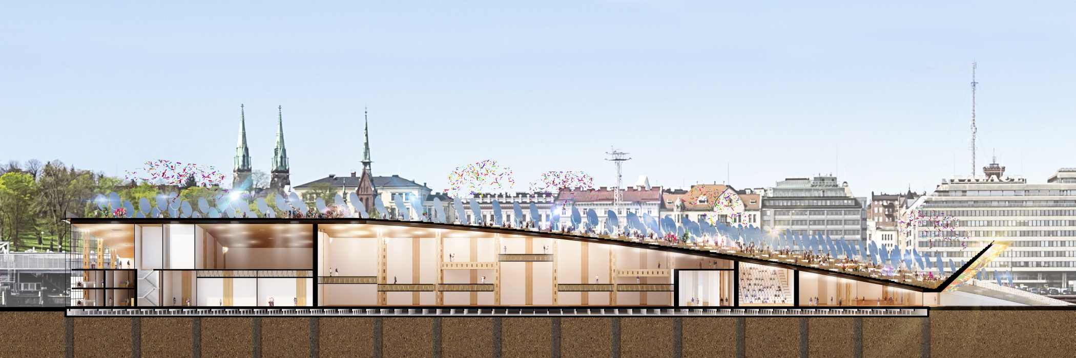
A gentle wooden roof promenade responds to the park hill across Laivasillankatu and prolongs the long array of public spaces stretching out from the city to the quays. It is the roof of the large wooden barn that shelters the museum. Its low-rise curved shape smoothly guides the prevailing winds.
This new urban square is populated with an orchard of simmering mirrors that follow the course of the sun. They take an active part in the city life, sparkling rays and droplets of coloured light at January Lux Helsinki night and playing with the dancers at Summer Festival. The entrance faces the city centre. A large mobile LED canopy hovers over the roof edge, as an interactive sign of the museum in the city.
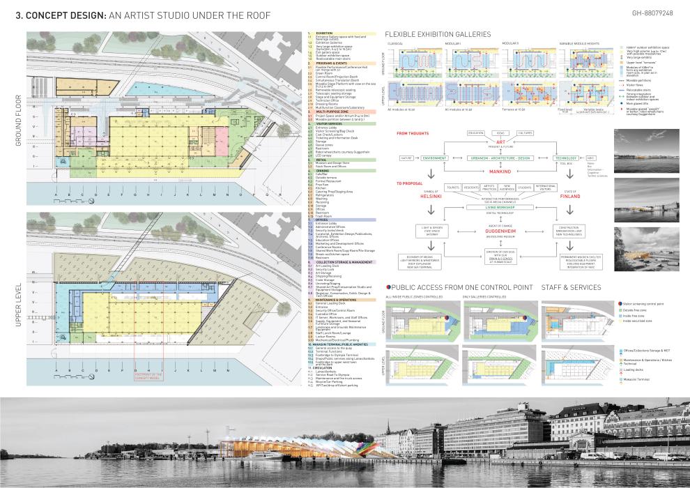
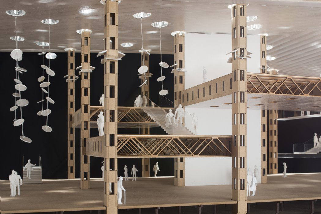
Ever-changing art requests extreme flexibility
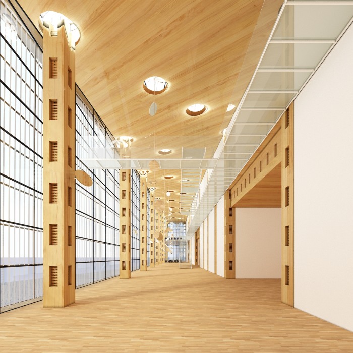
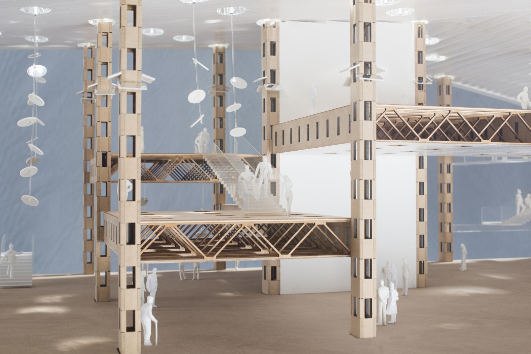
Art is changing at a fast pace. It is of crucial importance that the building is able to provide, upon demand, a very wide variety of spaces. Flexibility is the key and this project extends the concept to the structure itself, in the form of wooden 9 x 12 m “caisson” floors resting on hollow wooden columns housing all services (HVAC, fluids, electricity and IT). Each floor module may be displaced vertically at any height in order to generate numerous combinations of spaces of various shapes. A more traditional column-free 36 x 24 m exhibition space is also foreseen. This “Lego-ïd” building system is sheltered under the monolithic roof, at the heart of the chest.
The peripheral spaces at the junction with the city, in close interaction with the outdoor exhibition space, may also be arranged in many different ways.
Light!
Art display in convertible large rooms leads naturally the design to a monolithic volume with, accordingly, a reduced external surface where light can enter the building.
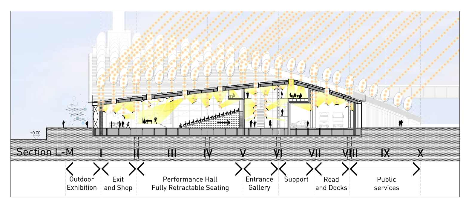
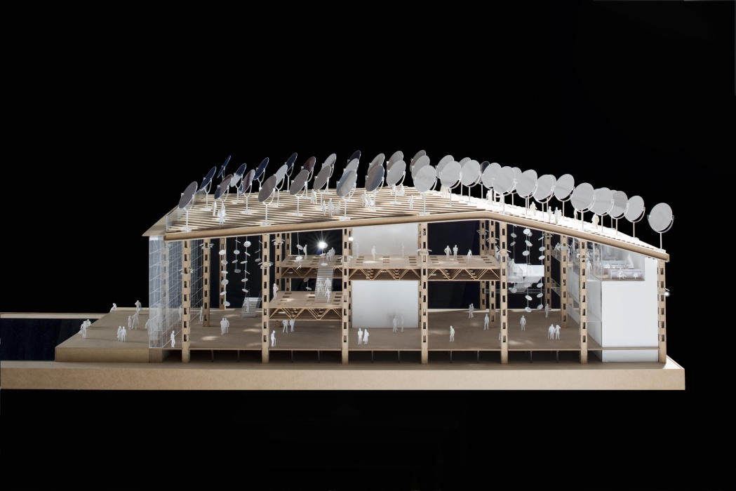
But light, in particular natural lighting, is of such importance in contemporary art that it deserves special care to bring it deep into the heart of the building. This is the rationale of the heliostat mirrors on the roof. They flood the museum spaces with daylight, making it bounce on various sets of adjustable suspended mirrors. This allows to design a specific atmosphere for each exhibition space: from black boxes with concentrated light beams to white open spaces with uniform light distribution.
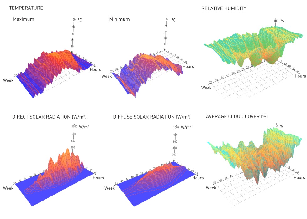
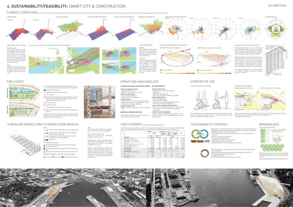
In search of real sustainability
Art may not escape the reality of unbalanced distribution of resources on earth. This is why the design aims at sobriety, functionality and economy: this is the basic approach to sustainability.
Structure
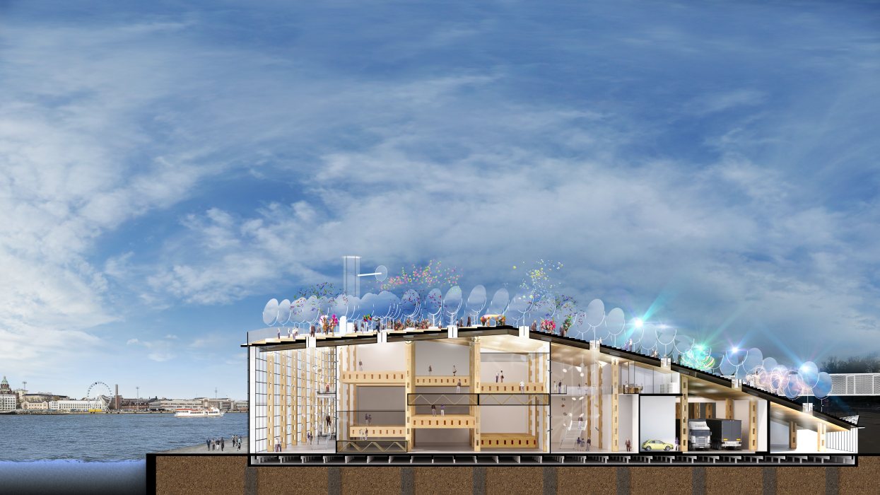
Besides the concrete structure around the lorry road and loading docks, the whole main structure is made of massive Kerto laminated wood slabs and profiles, protected by a highly insulated envelope.
Roof
The structure of the roof esplanade is made of a continuous, 70 cm high caisson: 10 cm thick Kerto slabs form the continuous, yet perforated, upper and lower flanges of the caisson, while regularly distributed curved 50 cm high ribs form the webs.
For natural daylighting, the roof is perforated with 3 elliptic openings (1,35 m x 1,80 m) in each roof module, one of these openings being placed on top of each column.
The free span of the roof is 9 m x 12 m, except in a very large exhibition space (axes C–E/II-VI) where one single span covers an area of 36 m x 24 m.
The roof is composed of a vapour barrier in recycled aluminium, 34 cm rockwool thermal insulation, a waterproofing membrane and a walkable deck arranged in steps of 15 cm, out of thermally modified Finnish timber.
Columns
Tubular ladder columns, on a regular 9 m x 12 m grid support the roof caisson as well as all floor plates.
With an outside section of 75 cm x 100 cm, each rectangular “tube” is made of four 22,5 cm x 35 cm profiles linked, every 1,5 m in height, by 75 cm high, 15 cm thick and 30 cm long blocks.
The blocks support the main floor and roof beams.
The void in the column is used for the air ducts, the electrical wiring and water/drainage pipes.
Main floor modules
Each floor module, with a free span of 9 m x 12 m and a height of 1,5 m, weights 9,5 tons and is composed of:
– Two 150 cm x 15 cm longitudinal beams, spaced at 9 m distance and 11 m long.
– Ten transversal 9 m long warren trusses, spaced 1,20 m and with a maximum bar section of 10 x 10 cm, supporting an upper and lower continuous 5 cm thick plywood slab forming the floor and the ceiling.
They are drillable for the installation of art and temporary walls.
Regularly distributed rectangular inspection holes in the main beams, as well as in the floor and ceiling slabs, make the floor module permeable for equipments and for the “daylight” cylinders.
The modules between axes E–K/II-V are displaceable and may be placed every 1,5 m in height from 4,5 m up to 10,5 m.
90 cm wide stair flights may be located between the floor modules on the 1 m wide strip corresponding to the lines of columns (between the warren trusses). Two 2,7 m long flights allow for a 3 m level difference between adjacent modules.
Ground floor plate structure
A modular and flexible raised floor covers a 1,8 m high technical void, on a 3 m x 4 m grid of short concrete column resting on the 40 cm watertight concrete raft.
Pile foundations to the bedrock complete the structural system.
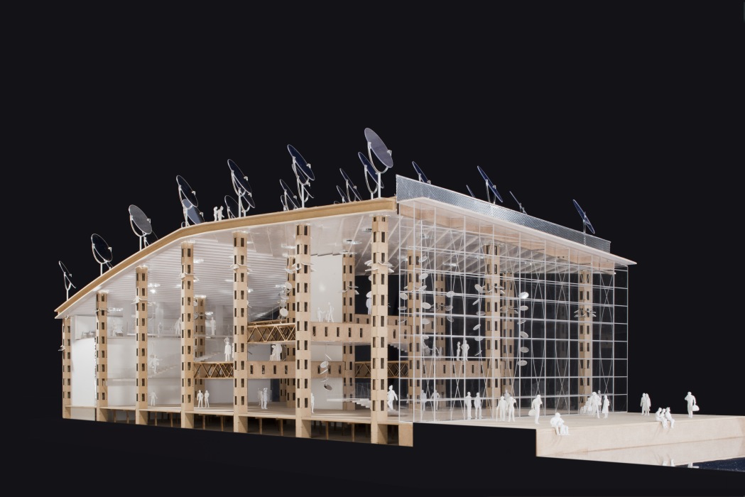
Facades
The North-East (to the quay), South-East (new Makasiiini terminal to Olympia), and South-West (along Laivasillankatu) façades are fully glazed, with a double skin.
Each skin is made of vacuum extra clear and transparent laminated double glazing volumes, 3 m long and 1,5 m high (with U = 0,3 W/m2K), in tiny steel frames (placed on the inner side of the double skin to avoid any thermal bridges).
They are hung in their corners to slender horizontal compression rods perpendicular to the façade and suspended, every 3 m, to a set of two opposed vertical parabolic cables spanning between the roof edge and the ground floor slab.
Sun louver strips, tracking the sun, equip the interior side of the outside double glazed skin.
The space between the two skins acts as a huge air duct to optimize the energy balance.
The strips are placed vertically when facing North-East, and horizontally when facing South-East.
Made of 30 cm wide transparent glass blades, with longitudinal white strips to block direct sunrays when perpendicular to them, the louvers present a solar factor G = 0,16, while still providing efficient daylight transmission and optical transparency.
Mirrors and skylights
341 mirrors in ETFE membranes (aluminum coated on both faces) are stretched on elliptical steel rings (3,75 x 2,8125 m).
Each ring rotates on its horizontal axis, clamped in two cylindrical motors.
The motors are fixed to a vertical fork on top of a 1,875 m high cylindrical post, which rotates on its axis, clamped in a third cylindrical motor. This motor is at the centre of the elliptical (1,80 m x 1.35 m) skylight.
Parapets and footbridge
50 % perforated stainless steel plates form the rectangular prism of the footbridge as well as the parapets of the roof esplanade and protect them from the wind.
Stairs
Galleries are independently accessible through the main entrance atrium (axes E–M/V–VI), which is also an exhibition space.
Running parallel to axis V, a light steel main longitudinal stair, 1,8 m wide and with a gentle slope of 1/3 (treads 15 cm x 45 cm), in a succession of flights each rising 1,5 m, lead to a balcony, also 1,8 m wide, giving independent access to each gallery module (also accessible to wheelchair robots).
The balcony itself is composed of 12 m long modules. Although normally set at level 7,5 m, it can be positioned at different levels to fit with the possible variable height of the ground floor modules. Secondary longitudinal or transversal stairs connect the various floor modules.
Lifts
Permanent classic glazed lifts connect levels 0 to 7,5 m (at axes E–F/V–VI).
Relocatable glazed lift shafts (of the “Easylift” type) may be placed locally to bridge the level difference between the floor modules.
Exit from the galleries
Galleries may be independently left, exactly on the same way as they are accessed, through the stairs, balconies, and lifts located in the exit atrium (D-E/II) leading to the café (B-D/I-II) or to the exit through the museum shop (K-M/I-II).
Walls
Wooden “Lego-ïd” cupboards form the walls located between the 0,75 m x 1,00 m ladder columns. They are 2,7 m (9 m span) or 3,6 m (12 m span) long, 75 or 100 cm deep and 3 m high (with fitting parts of 1,5 m height).
The walls are of three types: solid, double glazed or equipped with wooden louvers. They give view on the bay and are fitted with black cylinders transmitting daylight “beams” to local mirrors and objects.
Internal stairs
Movable stairs, for level differences up to 3 m, may be placed between the modules E-F / F-G / G-H /H-I / I-J / J-K when not at the same level, to ensure a smooth circulation flow between galleries.
Lighting
Natural zenithal daylight is extensively used as main lighting source.
The elliptical mirrors on the roof track the sun and reflect direct or diffuse light downwards through sky-lights, either :
– in each gallery module, through a light diffusing translucent membrane (the “classical” lighting in ancient museums);
– in the entrance and exit galleries, on a set of “floating” mirrors that reflect the light into the gallery modules through black cylinders to a second set of floating mirrors, projecting light beams on the exhibits.
This second set of mirrors might either be visible in the exhibition volume or hidden behind a perforated suspended fabric ceiling.
Artificial lighting takes over when daylight is lacking.
LOCALISATION
60°9’36,04”N / 24°57’19,07”E
SURFACES
Musée : 14.941 m²;
Makasiini Terminal : 1000 m²;
Commerces / Services publics : 620 m²;
Passerelle du parc: 270 m².
MAÎTRE D’OUVRAGE
Solomon R. Guggenheim Foundation
Organisateur du concours : Malcolm Reading Consultants
ARCHITECTES & INGÉNIEURS
Philippe SAMYN and PARTNERS sprl, architects & engineers Dr Ir Philippe Samyn
Chaussée de Waterloo, 1537 B-1180 Bruxelles Propriétaire exclusif des droits d’auteur (copyright)
Tél. + 32 2 374 90 60 Fax + 32 2 374 75 50
E-mail: sai@samynandpartners.com
ÉQUIPE
Architecture:
Philippe SAMYN and PARTNERS sprl, architects & engineers
Design Partner:
Dr Ir Philippe Samyn
Partner in charge:
Quentin Steyaert, Denis MéLOTTE, André CHARON
Collaborateurs:
K. AMMOR, M. BEVILACQUA, G. CARDILLO, A. CHICHIZOLA, N. DUCOULOMBIER, A. FACCIO, G. LORINI, S. NKAKA, O. OLIVIERS, M. OZHAN, P. RUARO, G. B. SILVA BATICAM, M. STOFFELS, C. VAN RAEMDONCK.
Techniques spéciales:
Philippe SAMYN and PARTNERS sprl, architects & engineers,
avec FLOW TRANSFER INTERNATIONAL sa
Rue du Ham, 137
1180 Bruxelles, Belgique
Tél. : +32 2 375 75 40
E-mail : info@fti-sa.be
Stabilité:
Philippe SAMYN and PARTNERS sprl, architects & engineers,
avec INGENIEURSBUREAU MEIJER bvba
Prins Boudewijnlaan, 53/2
2650 Edegem, Belgique
Tél. : +32 3 448 25 00
E-mail : info@meijer.be
Physique du bâtiment et énergie:
NEO & IDES
Rue des Chasseurs Ardennais, 3
B-4031 Liège (Angleur)
Tel. : +32 4 366 00 17
E-mail : info@neo-ides.be
Simulations dynamiques et microclimat:
CENAERO
Rue des Frères Wright, 29
6041 Gosselies, Belgique
Tel. : +32 71 910 930
E-mail: info@cenaero.be
Étude des flux de trafic:
AGORA sa
Rue Montagne aux Anges, 26
1081 Bruxelles, Belgique
Tel. : +32 2 779 13 55
E-mail: agora@agora-urba.be
Gestion des coûts:
Bureau Michel FORGUE sarl
Route de Charavines, 250
38140 Le Rivier d’Apprieu, France
Tel. : +33 4 76 65 19 34
E-mail : bureau@bmforgue.fr
Graphisme et signalétique:
SDESIGN sprl
Rue Armand Campenhout, 61
B-1050 Bruxelles, Belgique
Tel. : +32 2 340 96 80
E-mail : info@sdesign.be
Consultant cuisine et restauration:
F&BO consulting
Freddy OUSHOORN
Doornzeledries, 122
9940 Evergem, Belgium
Tel. : +32 475 26 71 39
E-mail : fbo@telenet.be
Consultant Finlandais:
Erik SALVESEN
Norra Elsplanaden, 2
00130 Helsingfors, Finlande
Tel. +358 9 6162 1228
E-mail : salvemax@mac.com
Consultants Mathématiciens:
Simone GUTT et Michel CAHEN
Tenbroek, 13
1640 Rhode-Saint-Genèse, Belgique
E-mail : sgutt@ulb.ac.be, mcahen@ulb.ac.be
DOCUMENTATION
Gestion documentation:
Philippe SAMYN and PARTNERS (A. CHARON et Q. OLBRECHTS)
Image de synthèse:
POLYGON graphics cvba (S. STRAGIER)
Get Directions


For plans sections and elevations, please refer to the archives section of the site available from the “references” menu.