415-Pedestrian footbridge – NMBS
LEUVEN
BELGIUM
140 m free span
first bridge (bidding documents ready) (2001-…); (01-415).
At design stage
– Architecture
– Mechanical, electrical, plumbing engineering
– Structural engineering
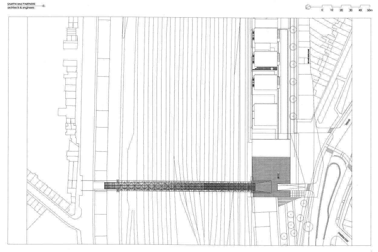
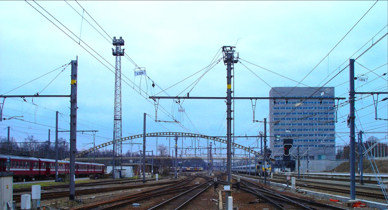
The railway Brussels-Liege is a North-South physical cut between the cities of Leuven and Kessel-Lo. Only a few uncomfortable bridges an tunnels for pedestrians and bicycle riders are crossing the lines.
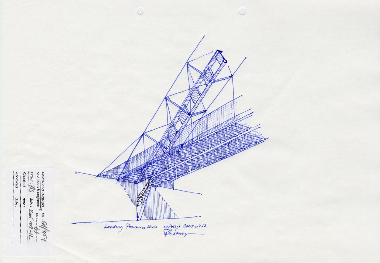
The city of Leuven and the ” Nationale Maatschappij der Belgische Spoorwegen ” (NMBS) have thus decided to build a sheltered footbridge for pedestrians and bicycle riders near the ” Provinciehuis “.
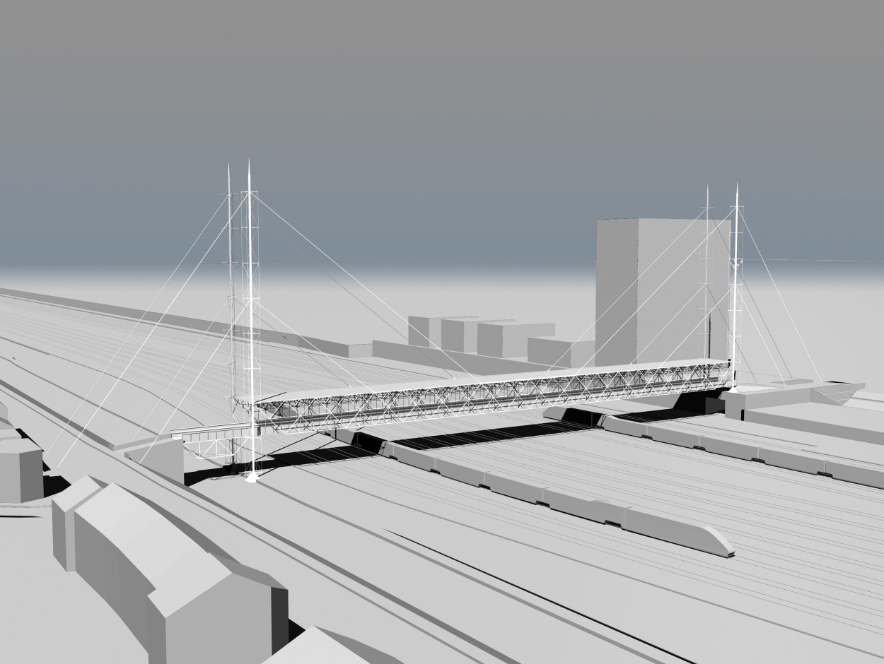
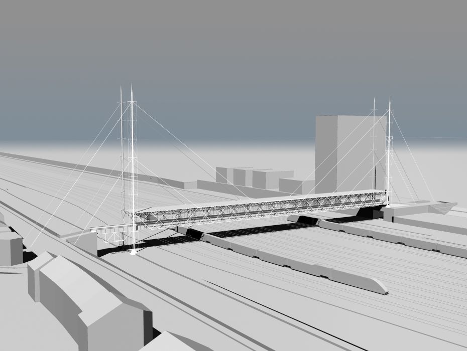
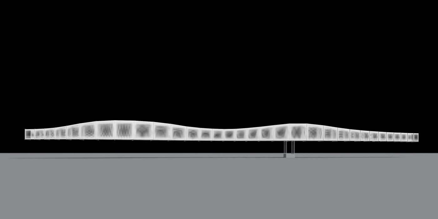
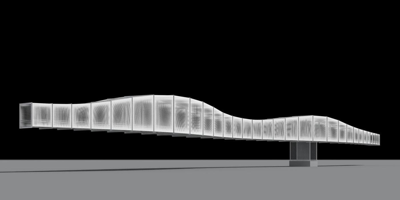
The site allows a perfectly horizontal footbridge design. The clearance above the lines demands a bridge flooring as thin as possible to allow harmonious connection on grade level at the bridge’s ends. The spacing between each of the 25 lines is small and doesn’t allow intermediate supports. The highspeed and normal railway traffic cannot be interrupted and imposes thus the launching of the structure above the lines without any interferences with them.
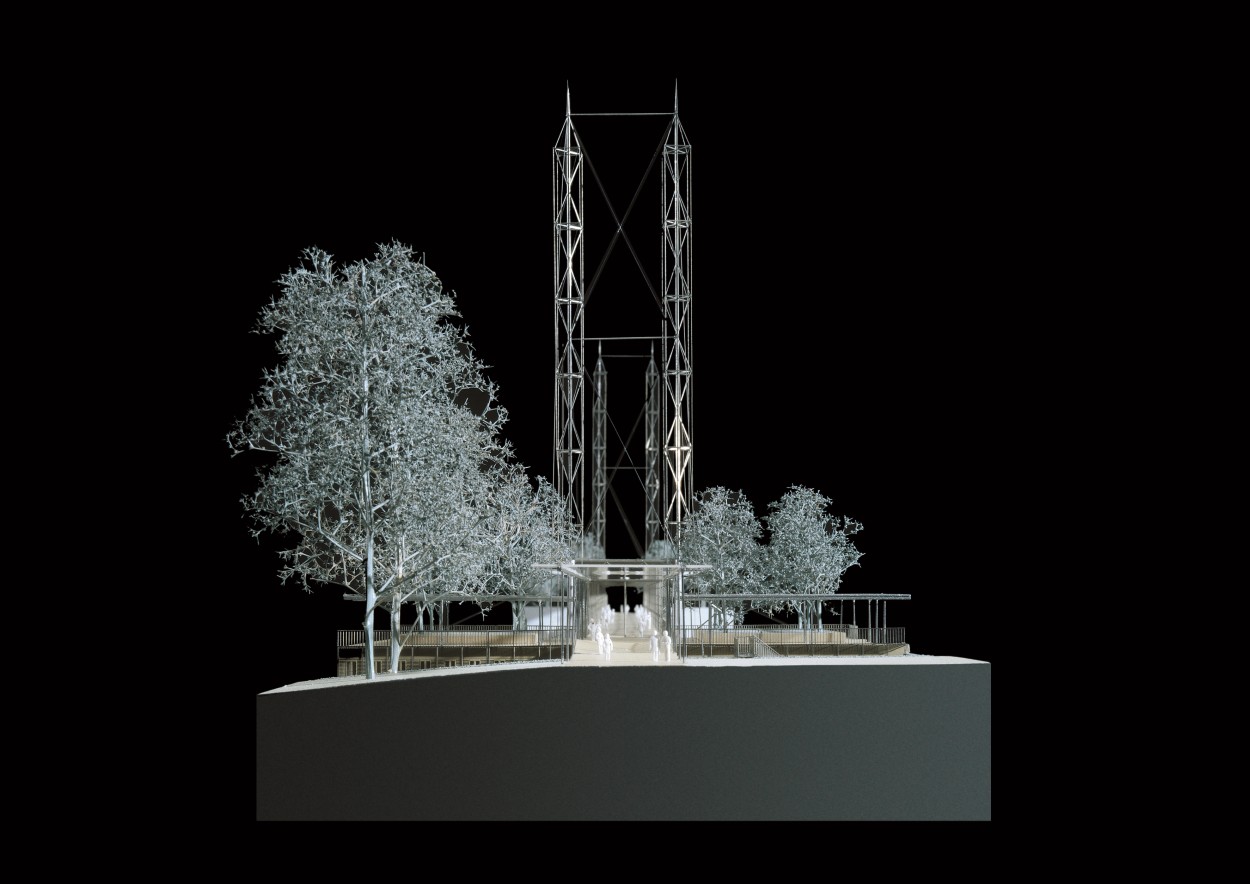
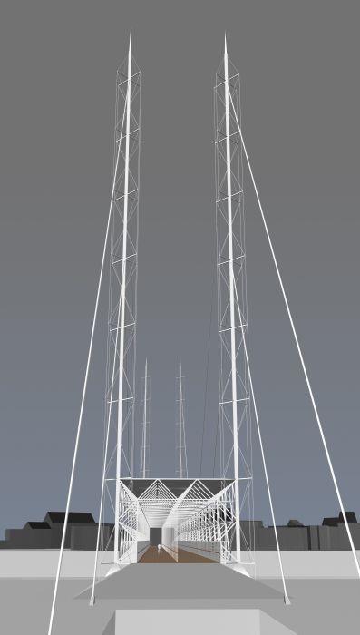
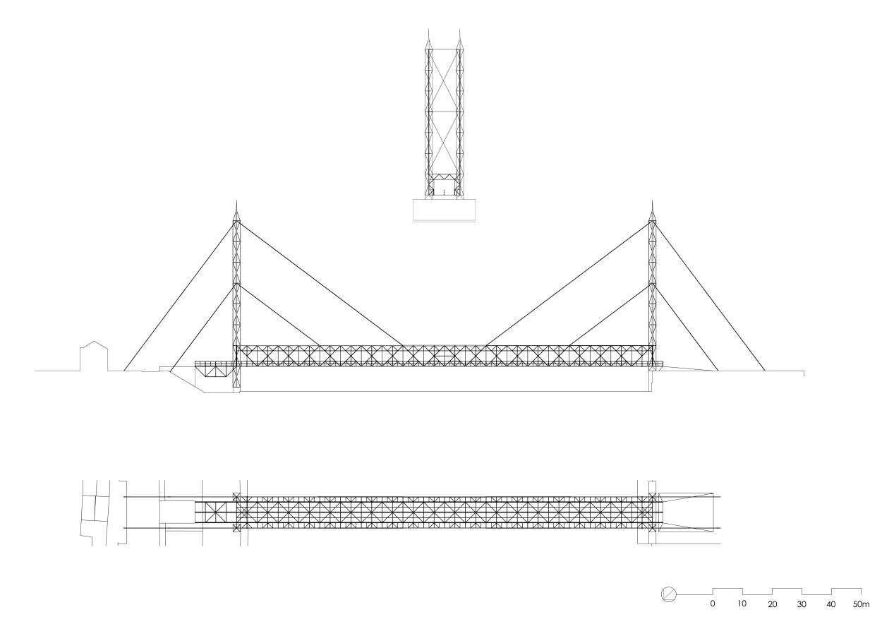
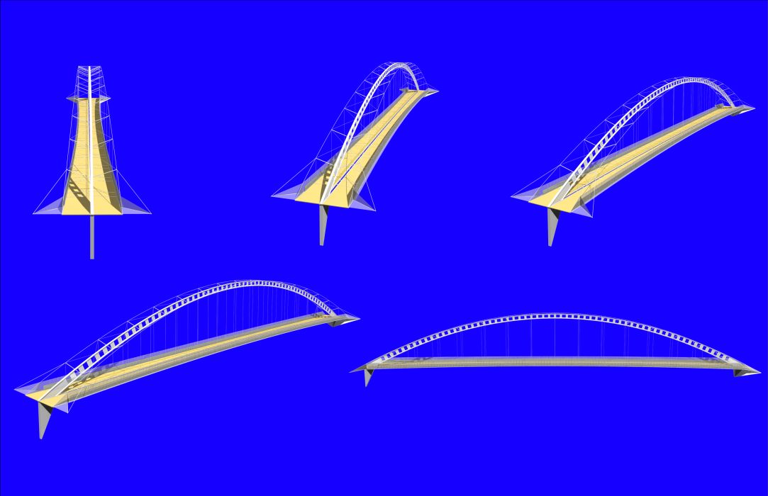
These restraints have led to the conception of a guyed pair of multi-trusses as light as possible, and with a 140 m free span between supports.
The two trusses hang to the cables every 28 m. They are made of twenty 7 m high on 7 m long meshes.
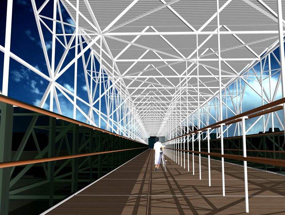
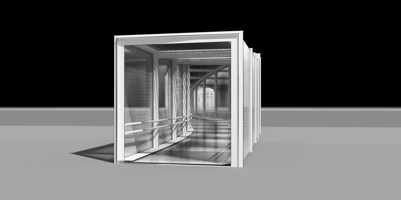
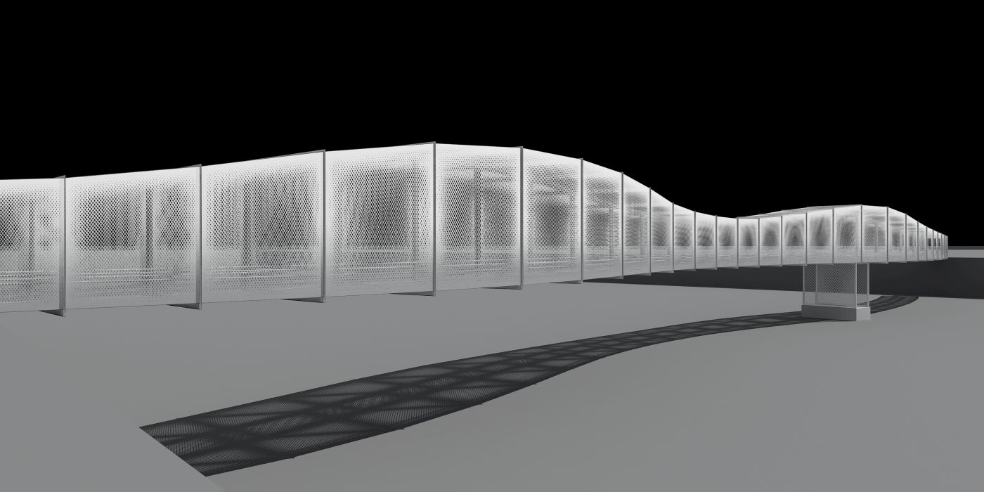
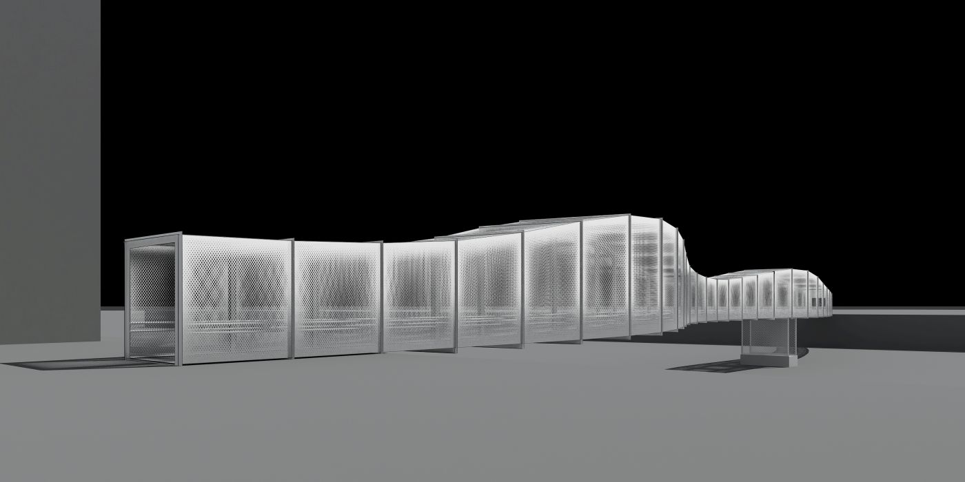
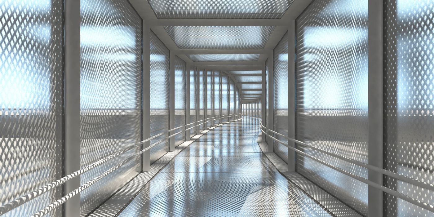
The transversal cross section of the structure is made of a 10,5 m wide trussed frame in the shape of an inverted U, bearing the 7 m wide bridge deck on its both sides and at its centre. The deck has a thickness limited to 8 cm, and, is made of a perforated diaphragm metal sheet stabilized by a screwed wood flooring.
The platform’s sides are furthermore equipped with 1m75 high glazed safety rails.
The triangulation of the main trusses is also braced by the ” U ” shaped transversal frames which allows to limit the buckling length of all the tubes constituting of the structure and to limit their square sections to 100 mm by 100 mm (exception made of the segments of the upper chords between the cables).
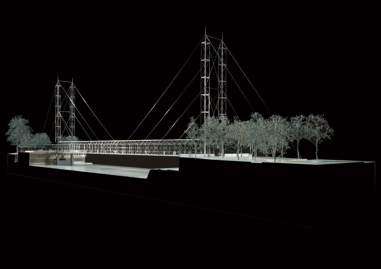
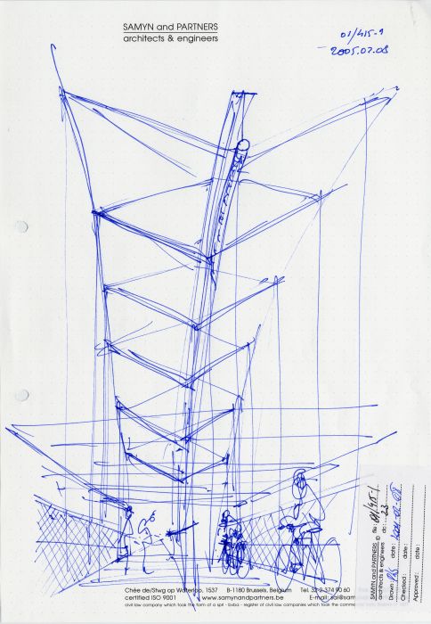
The cables with a ¾ slope on horizontal for the main span and a 4/3 slope beyond the supports are fastened to two pairs of 49 m high pylons.
These tubular pylons show a 300 mm large square tubular section and are braced against buckling by an array of little bars.
Guys disposition induces traction on the upper chord of the main turn on its three 28 m central segments.
The central segment of the upper chord shows a 200 mm on 200 mm section ; the adjoining segments 150 mm on 150 mm and finally 100 mm on 100 mm for the lasts two segments toward the supports ; the horizontal reaction at the guys ends is taken by anchoring masses situated respectively at 21 m and 36,75 m of the pylons.
Finally, the upper chords of the main trusses are hung with pendulum supports to the masts, allowing free thermal movements, their lower chords being fixed with axial dampers to the mast.
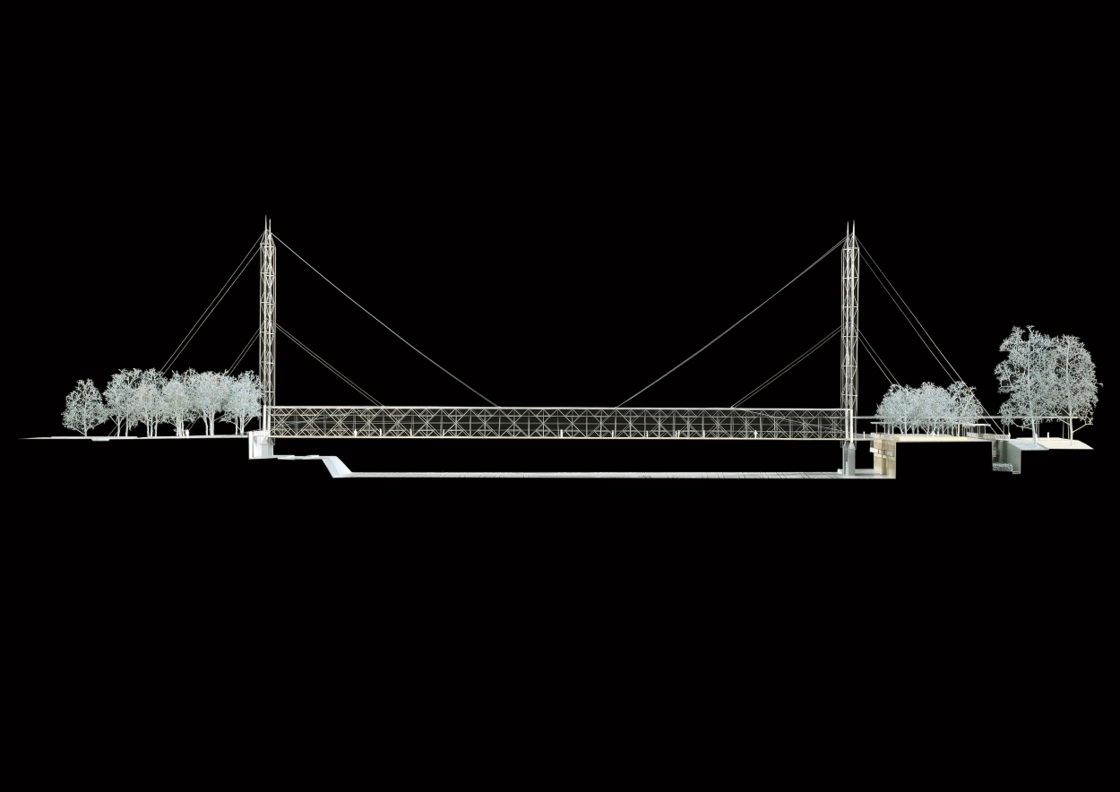
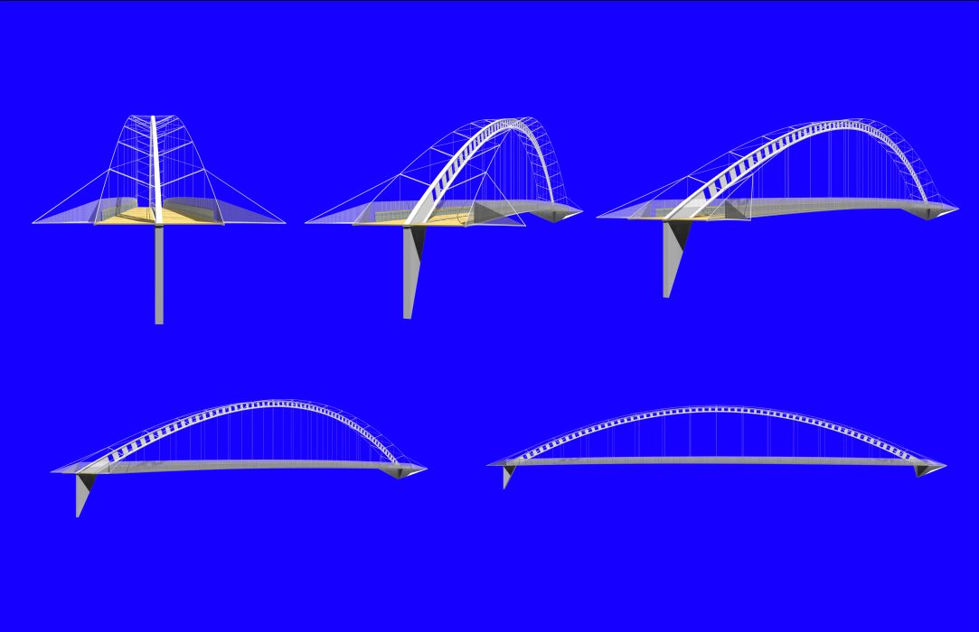
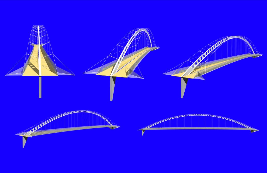
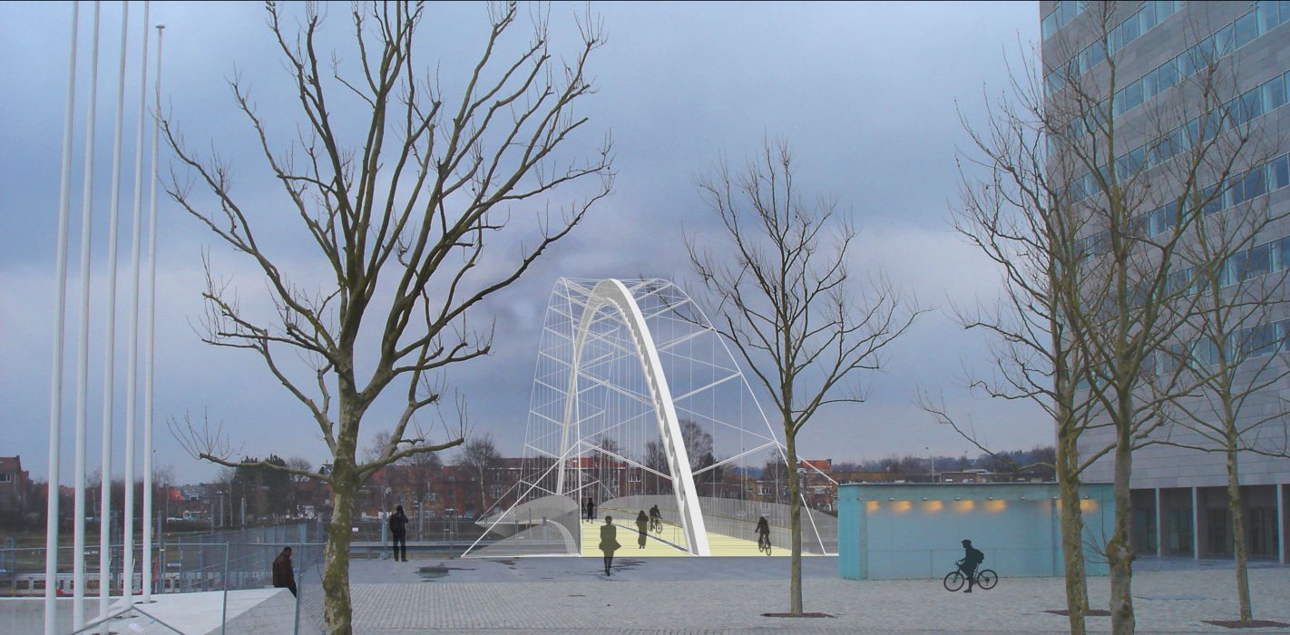
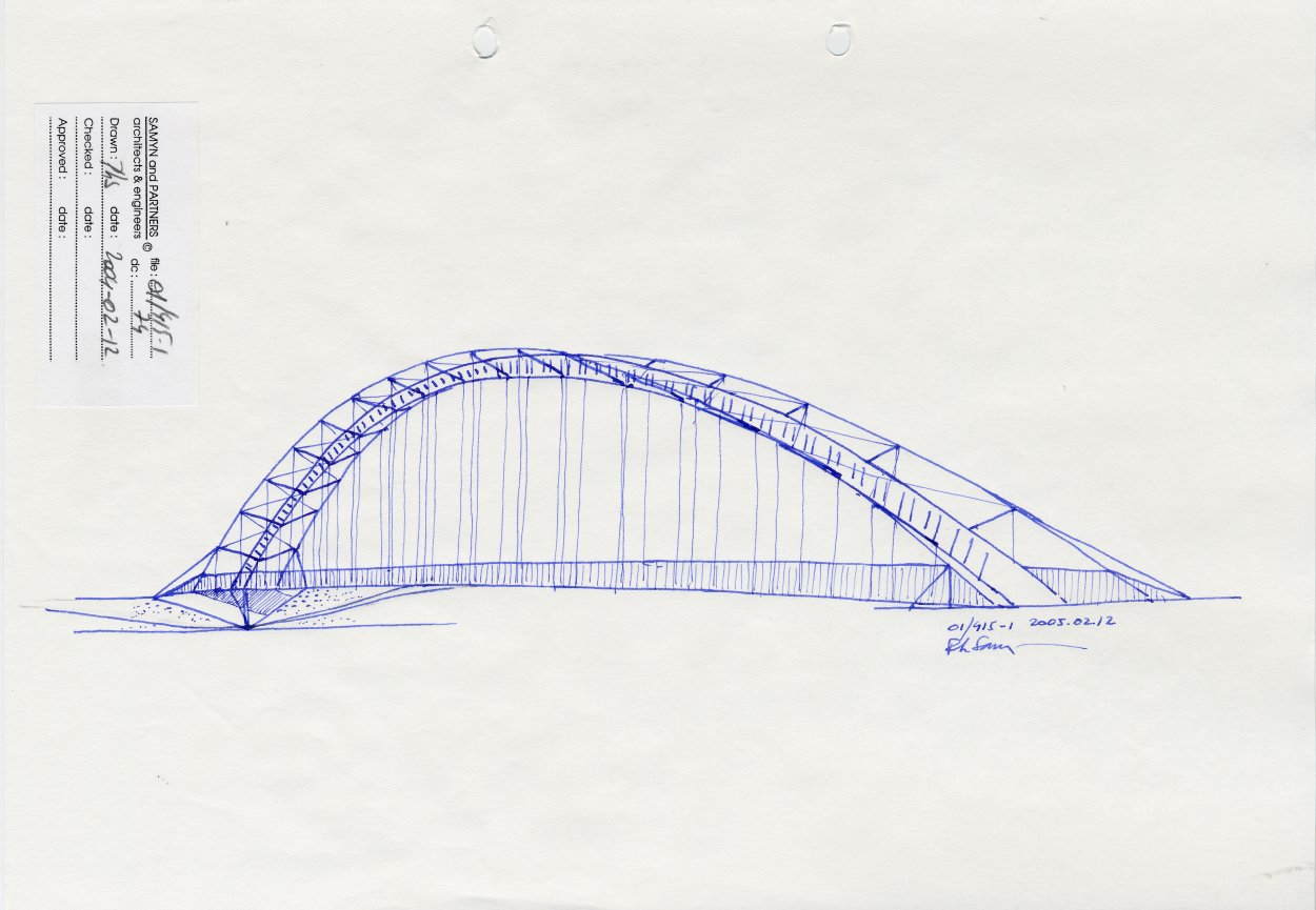
In January 2005, due to new real estate developments near the site alongside the footbridge, the authorities reconsidered its location. Given the new site, a new project for has been designed as an arch.
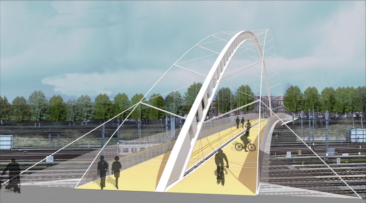
This steel arch, 20 m high, consists of a main welded reconstituted section using a flat metal plate 500 mm x 80 mm that forms the upper flange, a discontinuous web varying from 1.0 m to 1.5 m in height and a circular tube, 400 mm in diameter and 50 mm thick forming the lower part of the section. The proportions of this main arch are based on those used for the roof at the Leuven train station, and provide stability in its own plane.
Buckling of the arch is prevented by a system of braces developed in a study of guyed masts (done in collaboration with the VUB, department of structural mechanics) : 15 pairs of studs 120 mm in diameter welded at regular intervals of 8.75 m to the lower tube of the section, are connected to the upper wing of the arch by a set of cross cables 30 mm in diameter; these studs are also connected to a pair of tight cables 60 mm in diameter, anchored to the two ends of the bridge; their elevation corresponds to the curve of the arch and its projection in plan traces an arch of 140 m by 1.5 m. It can be demonstrated that by using this system, the buckling length of the arch is divided by 12, becoming 11.67m.
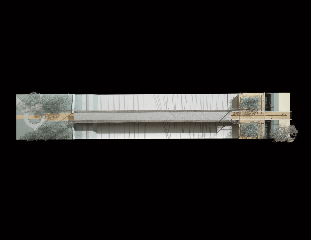
The bridge deck, whose width varies between 10 m and 7 m, consists of a stab in concrete with resin framed by a tubular or solid steel structure (120mm x120mm); its elevation traces an arch of 140 m by 0.9 m, and the plan draws a widening surface defined by two arches 140 m by 1.5 m symmetrical to the length of the bridge. It is supported three rows of 15 cables 24 mm in diameter connected to the arch, geometrically stabilising it and providing a separate circulation zone for pedestrians and cyclists. By increasing the number of cables, their diameter is reduced which means a significant reduction of weight for the anchoring sockets as compared to what would be needed if larger cables were used. Multi-strand cables give better internal damping and added metal helicoids strips prevent the risk of resonance. In compliance with safety requirements, the side walls along the deck consist of two metal plates, 2 m high, perforated for 50%, attached every meter to the lateral tubes borbordering the deck by steel bars 25 mm x 25 mm, and of a glass balustrade 1 m high.
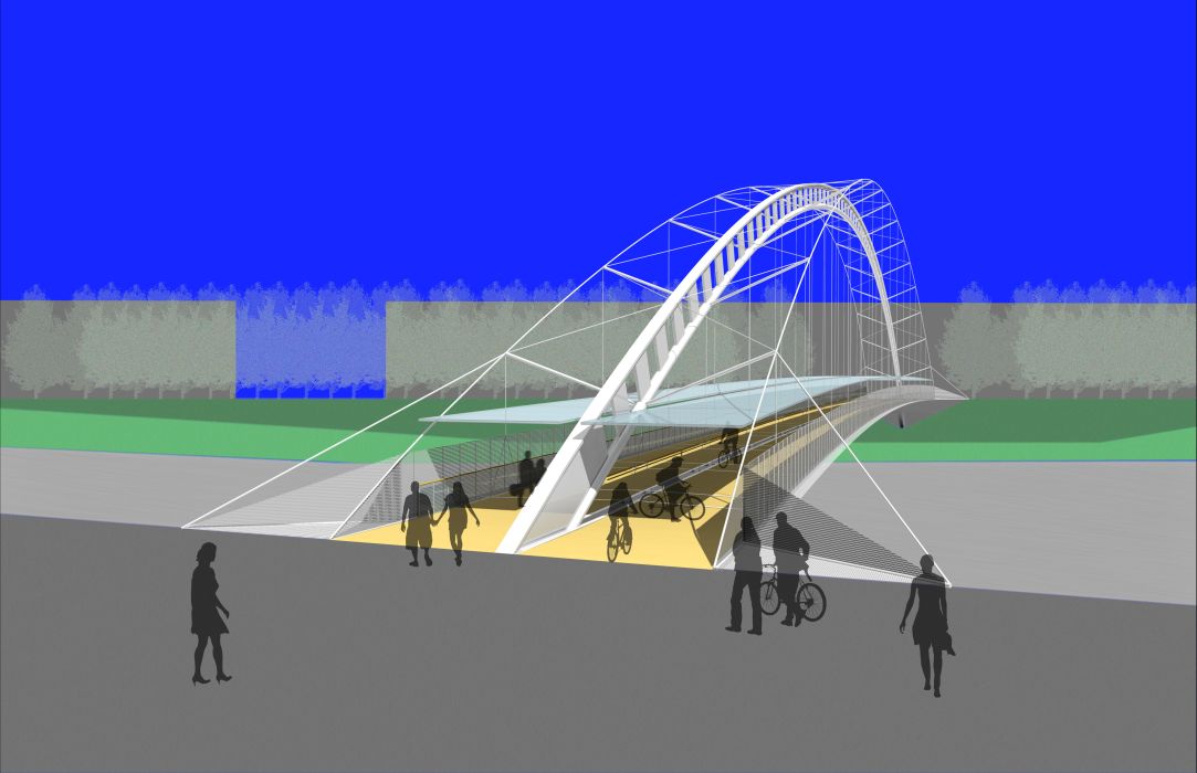
The effects of the wind on the footbridge are defined according to Eucocode 1. Thus, the lateral anchors at the foot of the arch prevent it from tilting under a side wind force of 160 kg/m; the curved shape of the deck, which is also clamped by triangulation at the ends, withstand a lateral wind force of 1200 kg/m on the sidewalls.
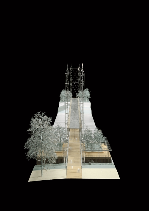
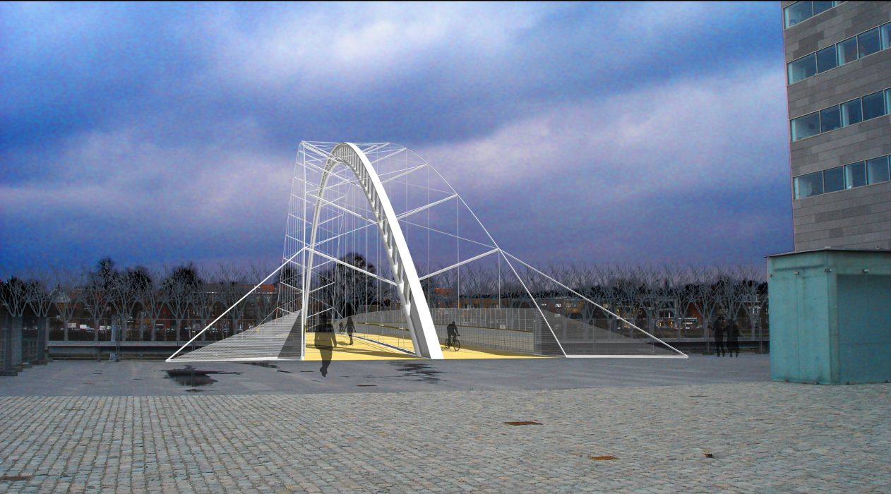
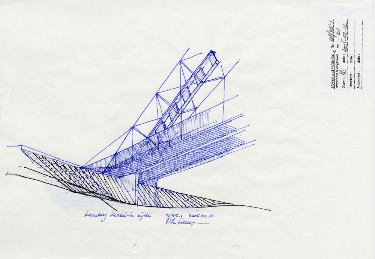
The footbridge made from a single braced arch can rest on a single concrete fin, visually much lighter than an abutment as wide as the bridge, providing descreet integration along the esplanade on the Leuven side.
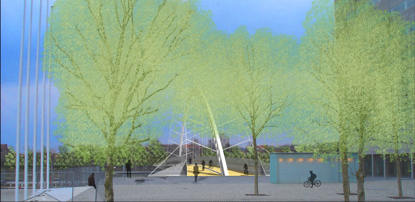
On the Kessel-Lo side, only the supporting fin wall plus a triangular talud plate occupy the embankment of the park, for gentle integration of the footbridge. In the summer, the leaves of the trees hide the top of the arch, an additional reason for keeping the base discrete.
The arch separates the pedestrian zone from the bicycle path. Right away or at a later date, the footbridge can be covered with a roof, preferably in glass, that can be attached very simply to the cables suspending the deck.
The minimum width in the centre of the footbridge of 2 x 3.5 m is imposed by the need to leave room for emergency vehicles; for the same reason, the useful height under the first button at the beginning of the arches (or under the roof if one is installed) is more than 3m.
Document E41_01/415 -En Issue of 2005-04-13
- Marc DUBOIS : “Tussen binnenstad en spoor – Leuven 2003 / Entre le centre-ville et le chemin de fer – Louvain 2003″ ; Philippe Samyn and Partners”, Ludion, Gent – Amsterdam, Janvier 2005, 128p., (ISBN 90.5544.548.7).
| 01-415 | footbridge, LEUVEN. |
| Client: | CITY OF Leuven, N.M.B.S. |
| Architecture: | Partners in charge : L. Gestels, B. Vleurick. Associates : E. Louis, S. De Love, L. Van de Velde, G. Verhaegen, |
Andrès Fernandez Marcos


For plans sections and elevations, please refer to the archives section of the site available from the “references” menu.