366-Bridge over the Leie
Kortrijk
BELGIUM
Preliminary design. (1998); (01-366).
– Architecture
2003.02.05
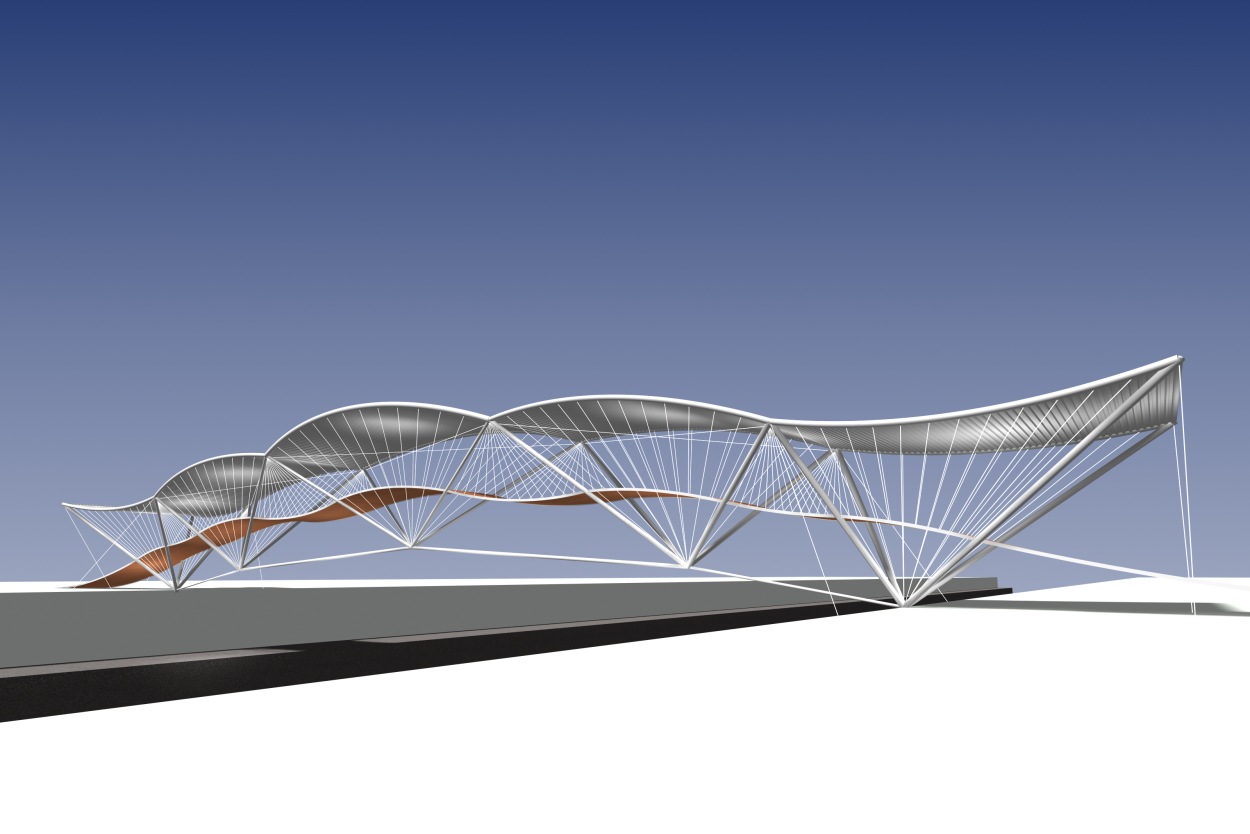
A) The 45 m span bridge aims to be of very low weight, achieving its strength and stiffness through the search of a proper morphology.
A.1) In a plane state of stresses, a truss beam represents the lightest and stiffest structural answer for a span to height ratio of nine.
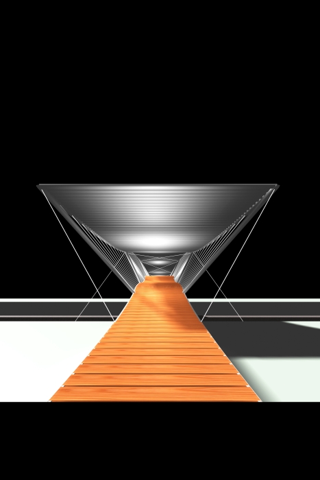
A.2) An equilateral triangular cross section of 5 m in height is more appropriate to cope with lateral loads than a rectangular one. A triangle on its base seems at first glanze to be a simple solution as it allows the deck to be located at base level. However, a triangle on its apex with the deck at mid height is preferable for many reasons : – the transversal span of the deck is equal to the net usable width of 2,85 m instead of spanning 5,8 m; – the deck braces the diagonal members of the trusses at mid height and thus reducing their buckling length by 3; – protection against windy rains can easily be achieved by a solid flat roof spanning between the upper chords and at the same time bracing them laterally whereas a triangle on its base requires, for the sake of the same elegancy, a sophisticated, expensive and difficult to maintain glass roof; – it provides a proper sun and glare protection during the day and an easy support for indirect lighting at night, enhancing a safe crossing.
B) The sequence of the form definition (or “finding process”) is the following one :
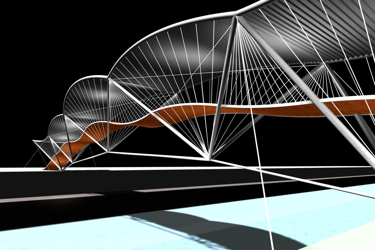
B.1) It has been shown, for a plane state of stresses, that a truss composed of isoceles triangles with a variable mesh size (named “harmonic trusses”) might be lighter than the lightest truss referred to as a warren truss. For a span having a span to height ratio of nine, a truss with four meshes – the two central ones being twice as wide as the lateral ones – represents the optimum optimorum, on the basis that all the external vertical forces are concentrated on the upper nodes and leaving buckling issues aside.
B.2) The transfer to the upper node of the uniformly distributed load on the deck at mid height of the truss, is achieved simply by an array of fanning tension rods. However, it is not yet satisfactory for the deck part on top of the lower nodes.
B.3) The buckling issues of the upper chord on the vertical plane and the hanging of the deck parts on top of the lower chords may easily be solved by curving the upper chord outwards and holding it, as well as the related deck part, by other arrays of fanning rods.
B.4) At this stage the horizontal deck is supported by a set of elastic tensile rods which need to be pre-tensioned to avoid compression resulting from the effect of the continuous beam on elastic supports. Curving the deck within a range of comfort suitable for pedestrians, the disabled, roller-skaters, baby carriages and cyclists resolves this problem.
B.5) Pedestrian bridges over rivers need to rise above ships’ masts and hulls and at the same time they have to ensure a gradual rise from each bank. A curved longitudinal profile allows this, while avoiding the disrupting effects of side lifts (disabled) or stairs (cyclists).
B.6) Rising and landing flights are thus required to end the design of the span. On each of the inclined trusses, two additional triangles with their upper chord curved inwards support, through fanning rods, an additional span as well as the required catenary risers on each side.
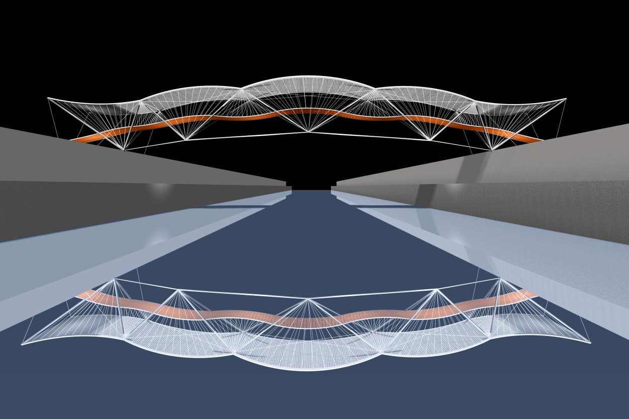
B.7) At bridge supports, lateral stability is ensured by two sets of tension rods holding the upper chords of the two inclined trusses to the ground.
B.8) Torsional stiffness is achieved by four compression bars and three sets of tension cross rods, linking the upper nodes of the two curved harmonic trusses.
B.9) The deck is simply composed of two metal U profiles into which 10 cm thick solid wood planks with open joints are fitted.
B.10) The roof is composed of a corrugated steel sheeting spanning 5,8 m on the lower side of the trusses upper chords and perpendicularly, a curved upper corrugated steel sheeting draining the roof on the upper side.
B.11) The diffused tensile rods system already ensures the major part of the safety parapet; it is complemented by additional safety devices.
- European Patent; 2000.04.05 N° EP. 0953684.B1. Bulletin of the European Pattent Agency 2000/14; 14pp. Den Haag; (Netherlands).
- AEDES: ” TRANS ARCHITECTURES 02 + 03: Cyberspace and emergant theories “; exposition catalogue; Berlin 98.08.03-22; (Germany).
| 01-366 | FOOTBRIDGE OVER THE RIVER LEIE, KORTRIJK. |
| Client: | City of KORTRIJK. |
| Architecture: | E. Krzeslo. |
For plans sections and elevations, please refer to the archives section of the site available from the “references” menu.