477-The International Polar Foundation
Toronto
CANADA
16.349 sqm; (2004); (01-477).
At design stage
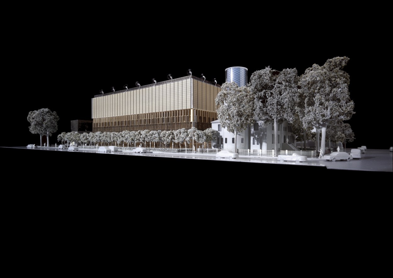
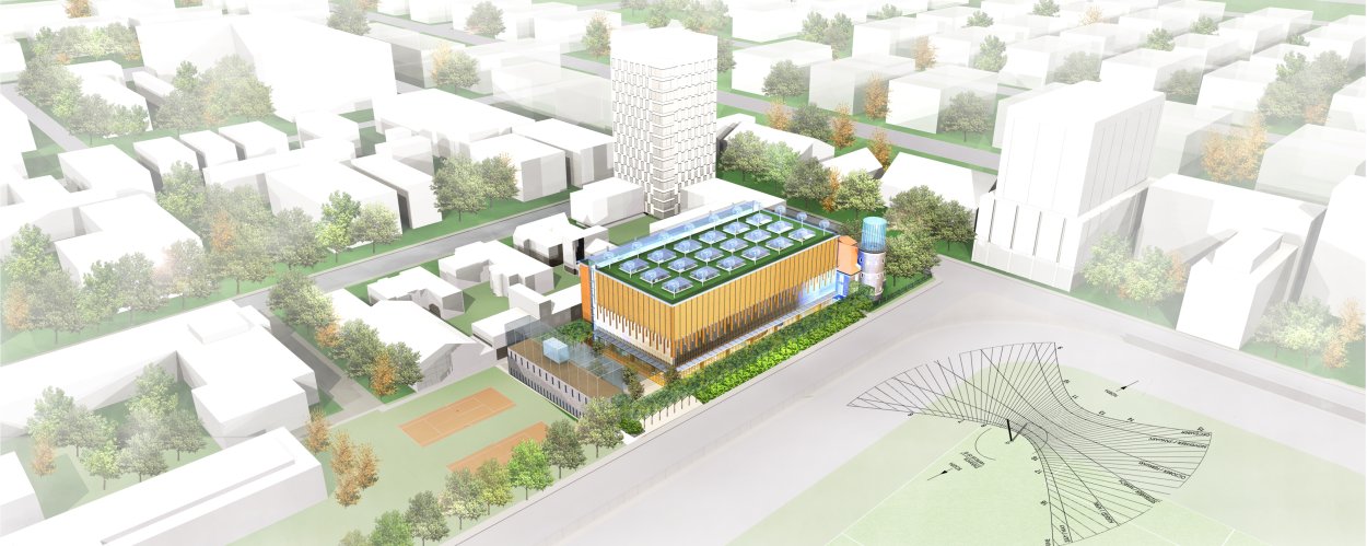
1. Layout and brief description
The complex consists of:
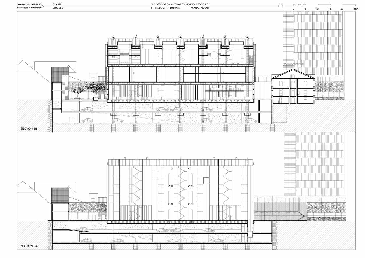
· a main building in three parts: an exhibition zone (A), a vertical traffic zone (B), a service zone (C),
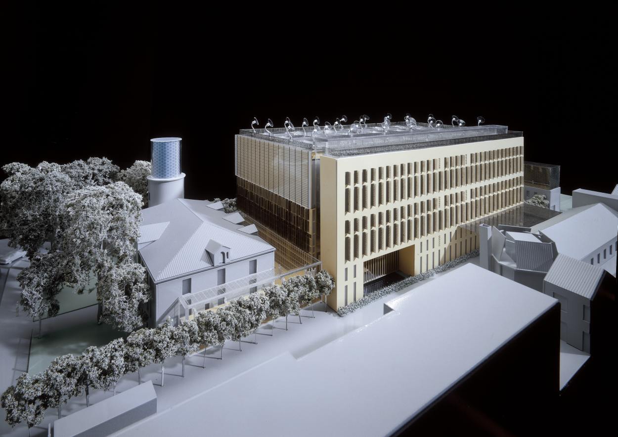
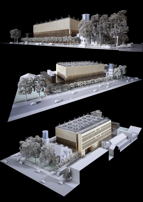
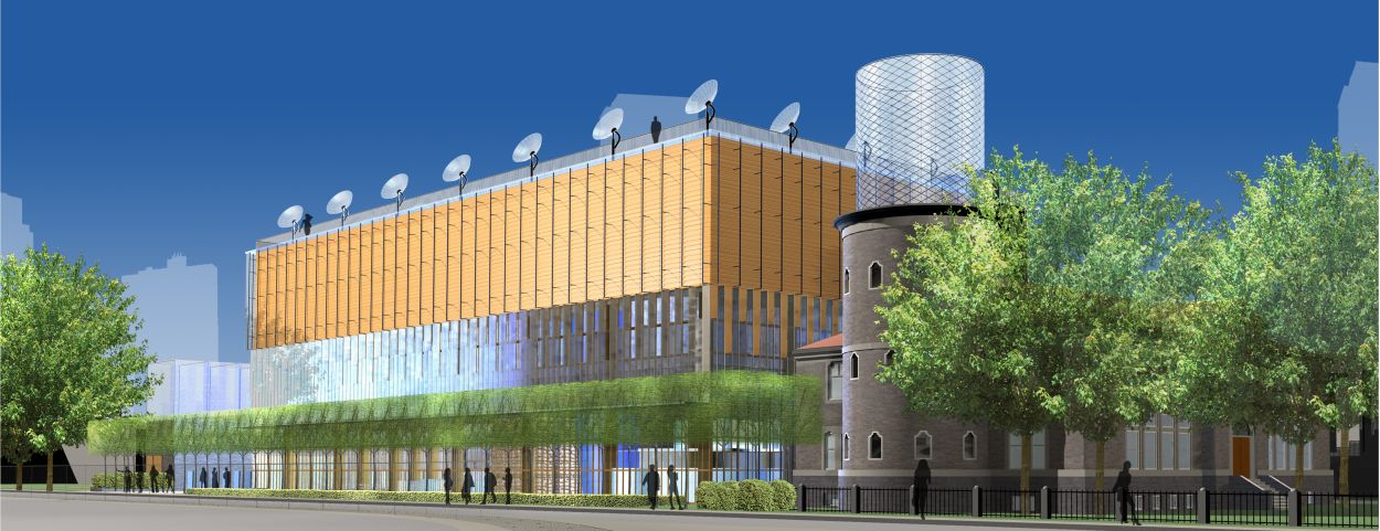
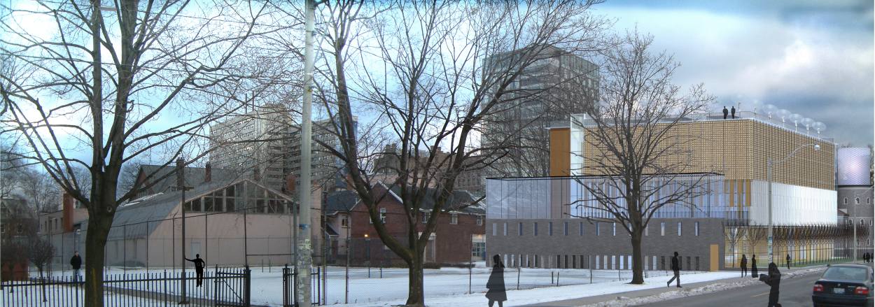
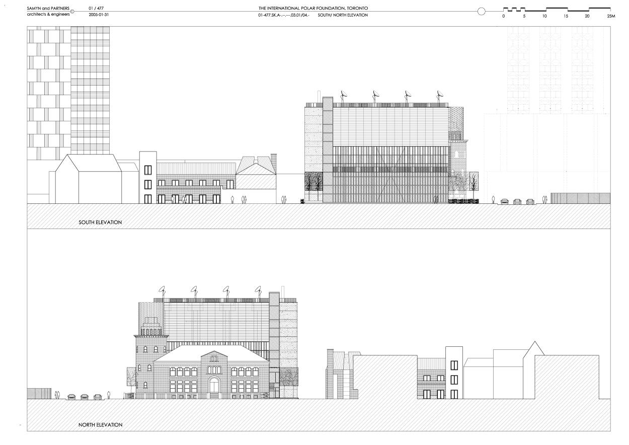
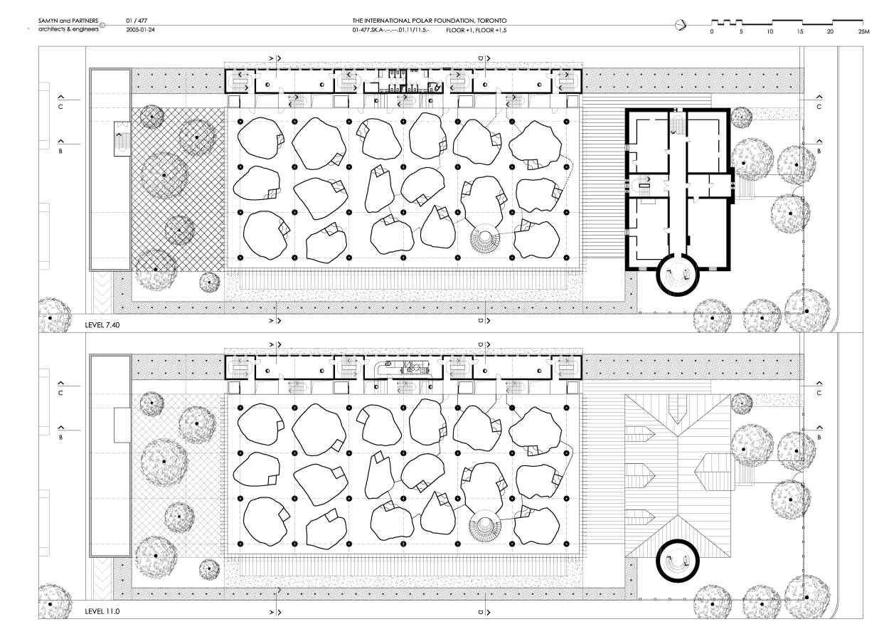
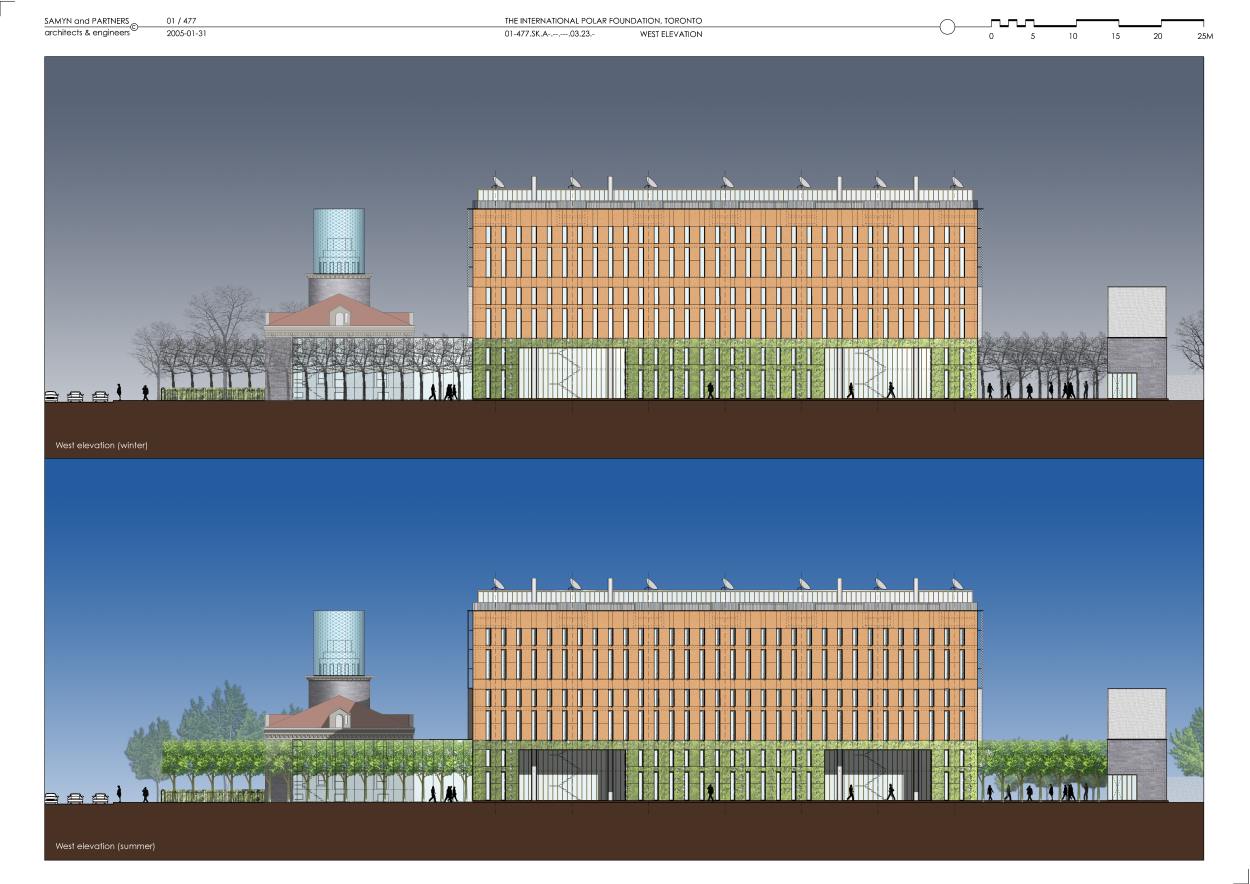
· the former building of the Canadian Meteorological Observatory, the tower of which has been raised, with its proper entrance (D),
· a glazed atrium linking the main building to the former and extending along the WESTERN side of the old building, also used as a second entrance (E),
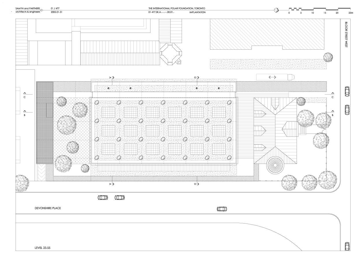
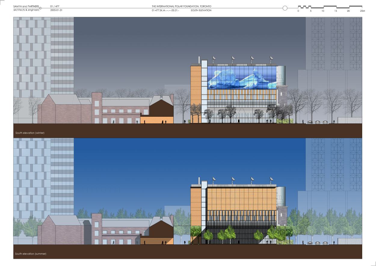
· a square to the SOUTH of the main building, where the main entrance is situated (F),
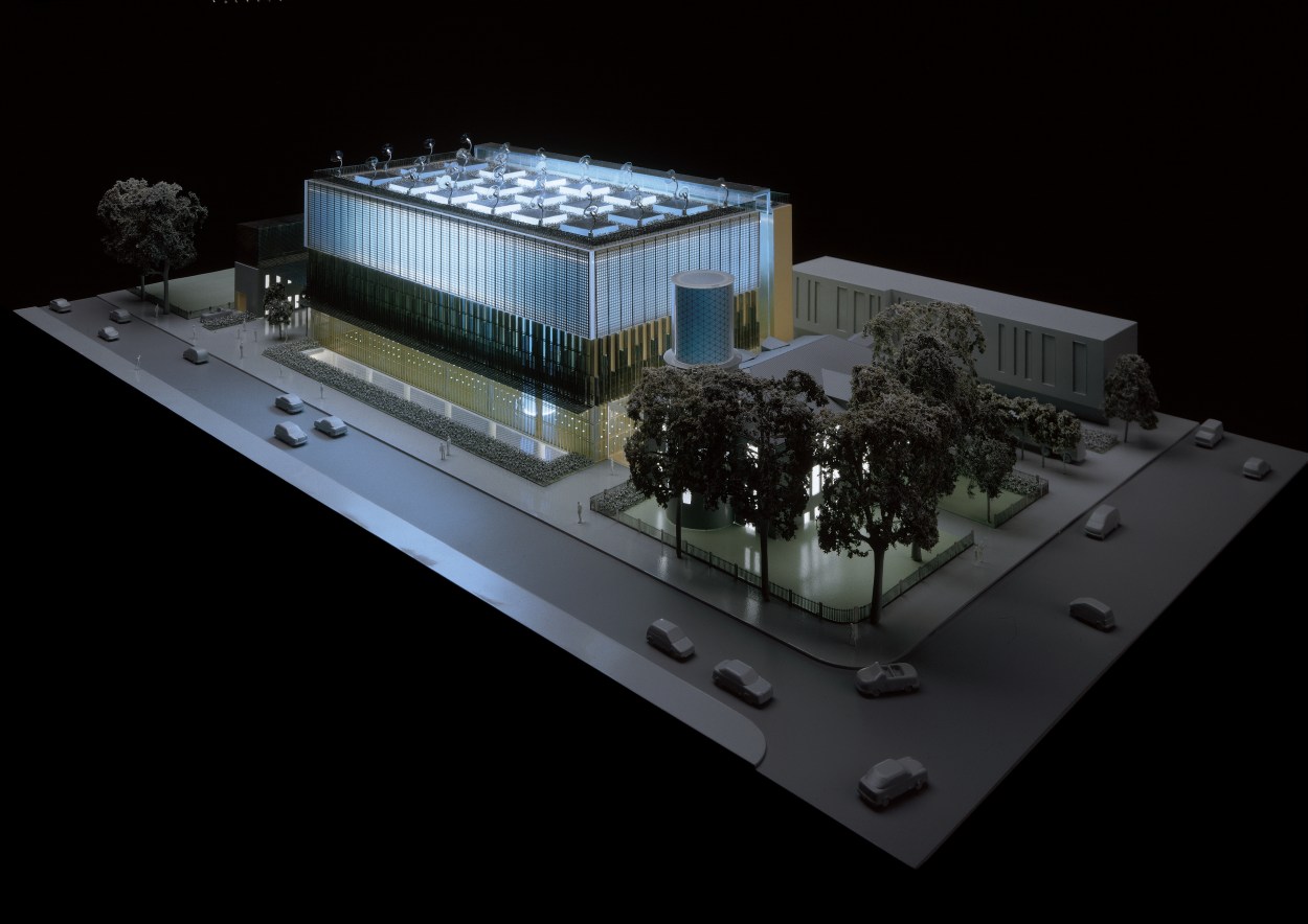
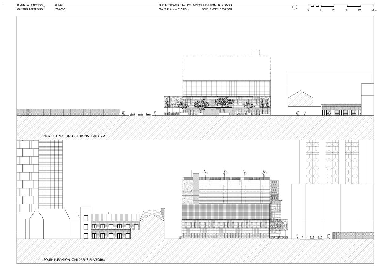
· on the SOUTHERN edge of the site, a small structure straddling the access ramp to the underground car park, including the children’s platform. This structure is covered by a supple “trellis” made of stainless steel -mesh. Akin to a silken veil, the “trellis” protects the play area on the roof terrace, and creates a microclimate (G). The “trellis” structure slows the flow of air, thereby preventing swirling winds on the square,
· A protective cover sheltering the section of the pedestrian zone between the main building and the college, to protect against draughts (H),
· Espalier trees along the EASTERN façade (I), fencing off the square (J), as an extension of service zone C, along the WESTERN façade, with the function of cutting off draughts and providing sun protection for the glazed areas on the ground floor of building D (K),
· A line of shrubs (L, M, N, O, P, Q) acting as a wind-break, also at the access to various delivery vehicles (O).
2. Internal layout
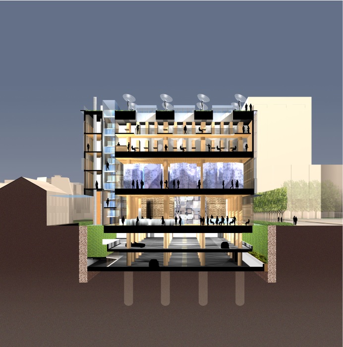
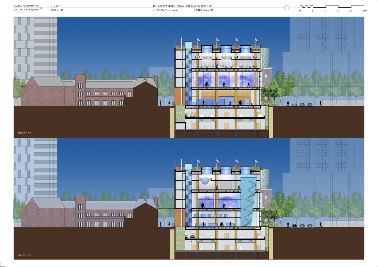
The main building consists of three display levels, each with mezzanine.
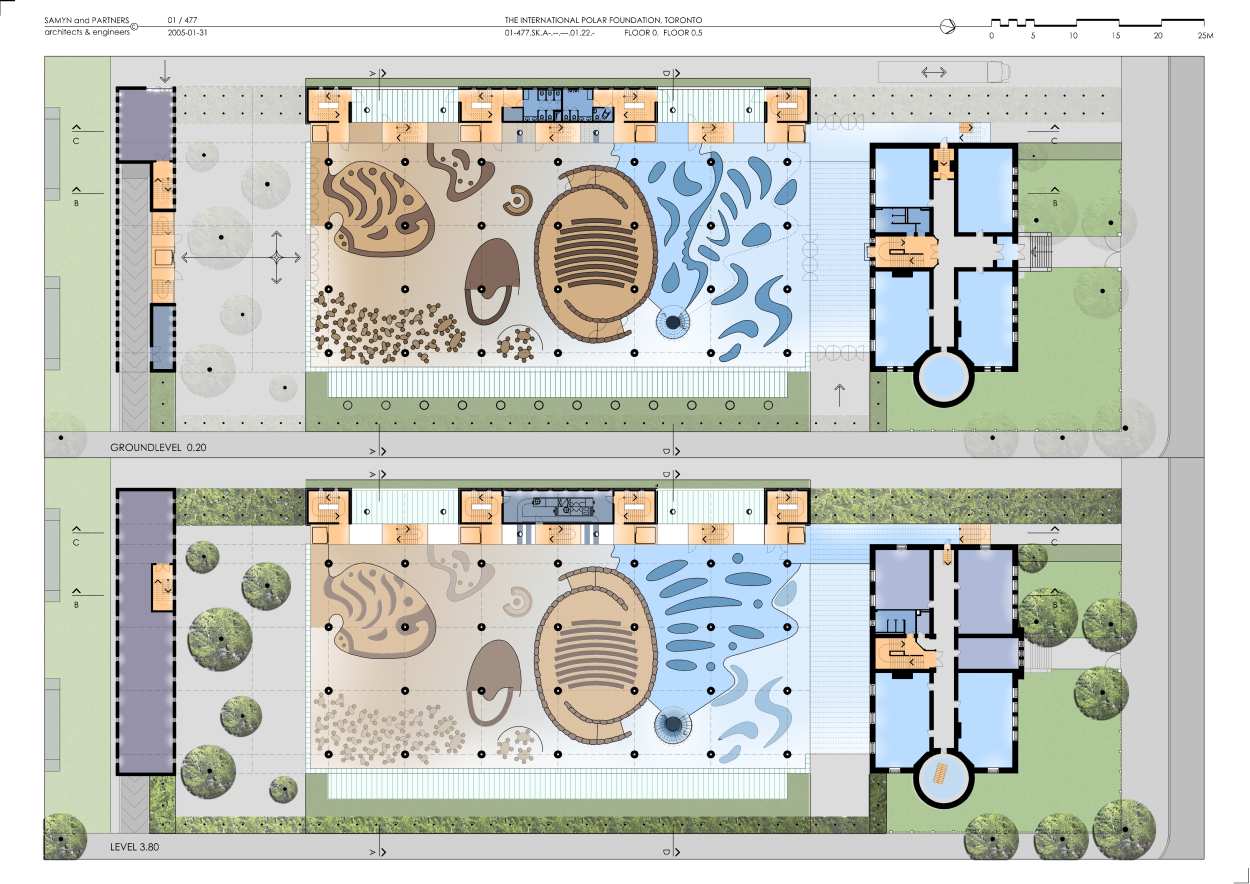
Level one houses the reception area, information desk, shop, cafeteria, auditorium, the beginning (which includes the Observed Climate Exhibit, then immediate transfer to the top level) and the end (the body of the Cone symbolising the ice-core pierces the entire building and culminates there) of the route for the permanent exhibition (which goes from top to bottom of the building), as well as a temporary display area linked to the atrium and the old building.
The mezzanine, specific to the NORTH of the auditorium, houses the Solutions Exhibit room, exploring possible responses to climate change and sustainable development issues.
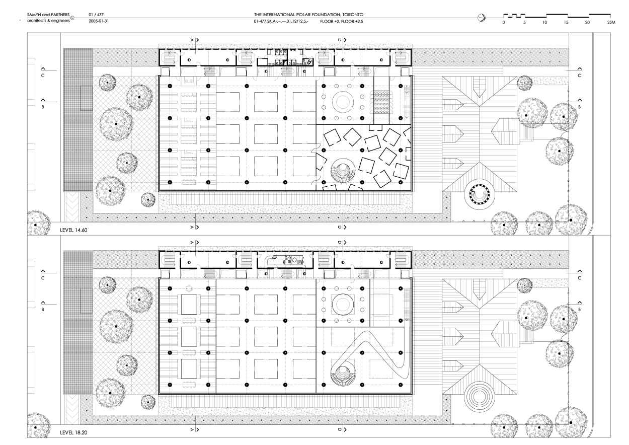
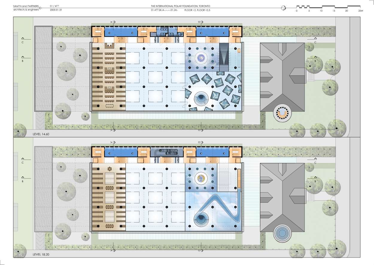
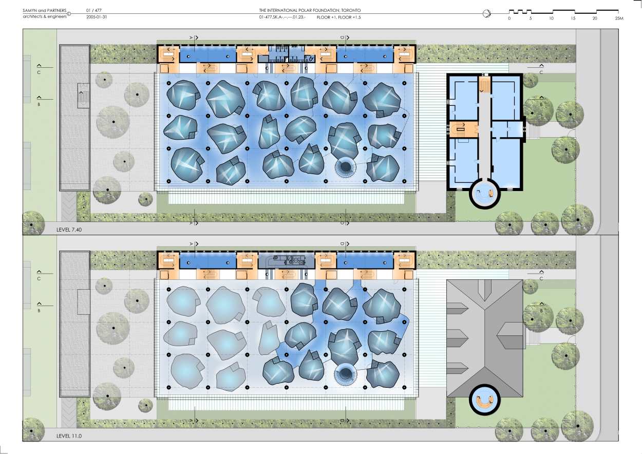
Level two houses the rooms of the present and the future, as well as the exhibition space dedicated to long term glacial and glacial periods, the permanent exhibition area and mezzanine, the rooms for recent ice-ages and ice archives. These areas are accessed from the Cone.
Level three includes, to the SOUTH, the documentation centre with mezzanine, a large, double-height exhibition area devoted to the complexity of the climate in the centre and, to the NORTH, the permanent exhibition area beginning, on the mezzanine by the Arctic room, from where the NORTHERN hemisphere of a large globe can be observed, continuing through to the area below, to observe the SOUTHERN hemisphere, board the “stratospheric plane” before coming back to the top of the cone, on the mezzanine level, on the ice-cap .
A large opening, on the WESTERN side of the exhibition areas and through the entire height of the building, contains the three main staircases and the four elevators. This enables visitors and passers-by to see the overall layout of the complex at a glance and provides orientation. It is also used for the vertical transport, for large display items arriving from the basement workshops.
The built area forming the WESTERN façade of the building acts as a weather shield. It contains emergency staircases, the sanitary areas, the administrative area, storage and technical rooms.
This means that the façade openings due West are limited to the necessary, the ground floor excepted, where two expansive glazed areas provide a pleasant view towards the exhibition rooms from the western pedestrian walkway and the classrooms of the opposite building.
· The former meteorological Observatory building has been allocated to administrative offices and permanent exhibitions relating to meteorology (the extended tower plays an important role in this).
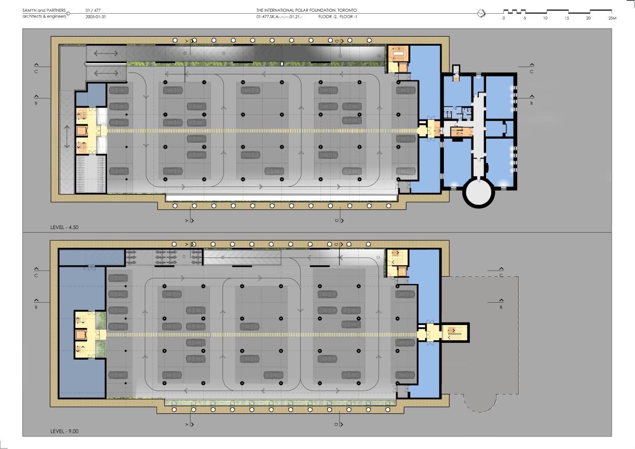
· Two basement levels provide parking for cars, bicycles and motorcycles. The basement also houses the storage and technical area, as well as the workshops. Natural lighting and ventilation is made available to the garage.
Horizontal, glass screens are set into the top of the EAST and WEST walls of the car park and fresh air intake (for former periods) is incorporated at the base of the second basement level. During cold weather, warm air is provided by air from the ventilation systems of the upper levels. Four flues extract exhaust fumes by naturally-assisted convection.
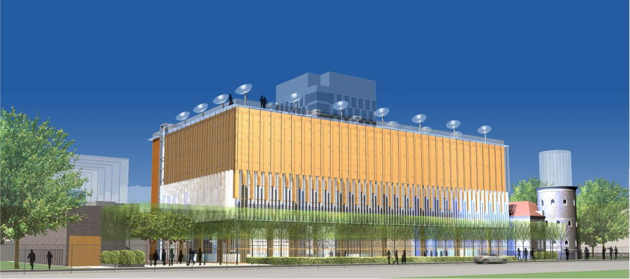
3. Exterior architectural expression
· All of the windows in the building, and of their frames, without exception, feature very high energy performance levels (K=0.3 W/m˛ °K) and colour rendering. The seal on these windows is highly efficient, the opaque sections having a K = 0.15 W/m˛ °K
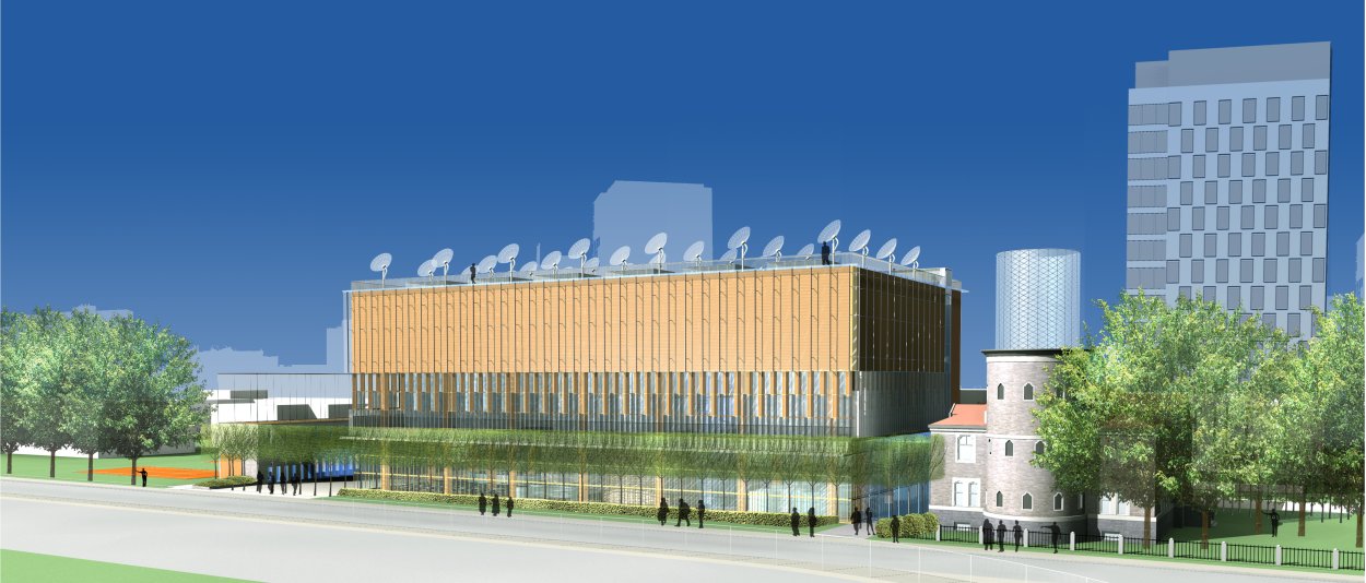
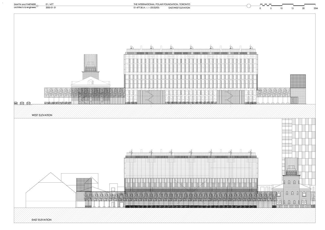
· The exhibition area is housed in an ascetic, rectangular volume clad with wooden panels.
· Level one, entirely glazed provides thorough views and is 6 metres high and has canopies and sun awnings on the EAST and SOUTH sides in a horizontal position during the summer, allowing the sun to penetrate in the winter when folded away vertically. Trellised trees protect the EAST side from the summer sun.
The façade of level two is divided into three strips, each 2 metres high. The first strip is completely glazed, the second 75% glazed and the third 50% glazed, thus modulating the amount of natural light. The full panels are made from wood and the glazed sections are fitted with motorised vertical blinds made from stainless steel fabric, which allow the luminosity and solar gain to be controlled. They also protect the wood from heavy precipitation.
The façade of level three, which has overhead, natural lighting, is entirely opaque and clad with wooden panels. Light emitting diodes are incrusted in a very close, screen pattern into the expanse of wood, transforming them into luminous screens. A wall of glass slats, enhanced by a small strip of glazed roof, protects the timber facing and parts of the façade on the lower levels from the rain and snow.
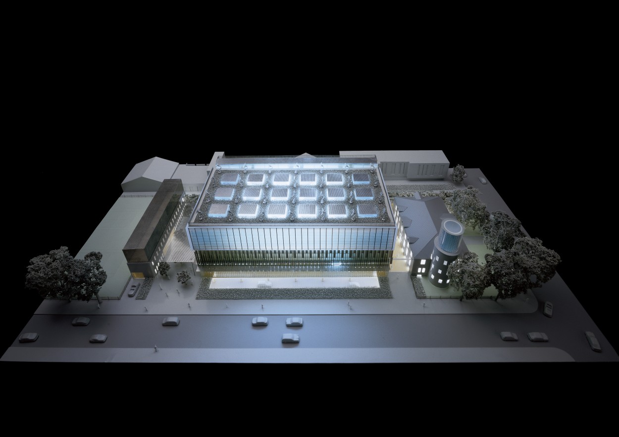
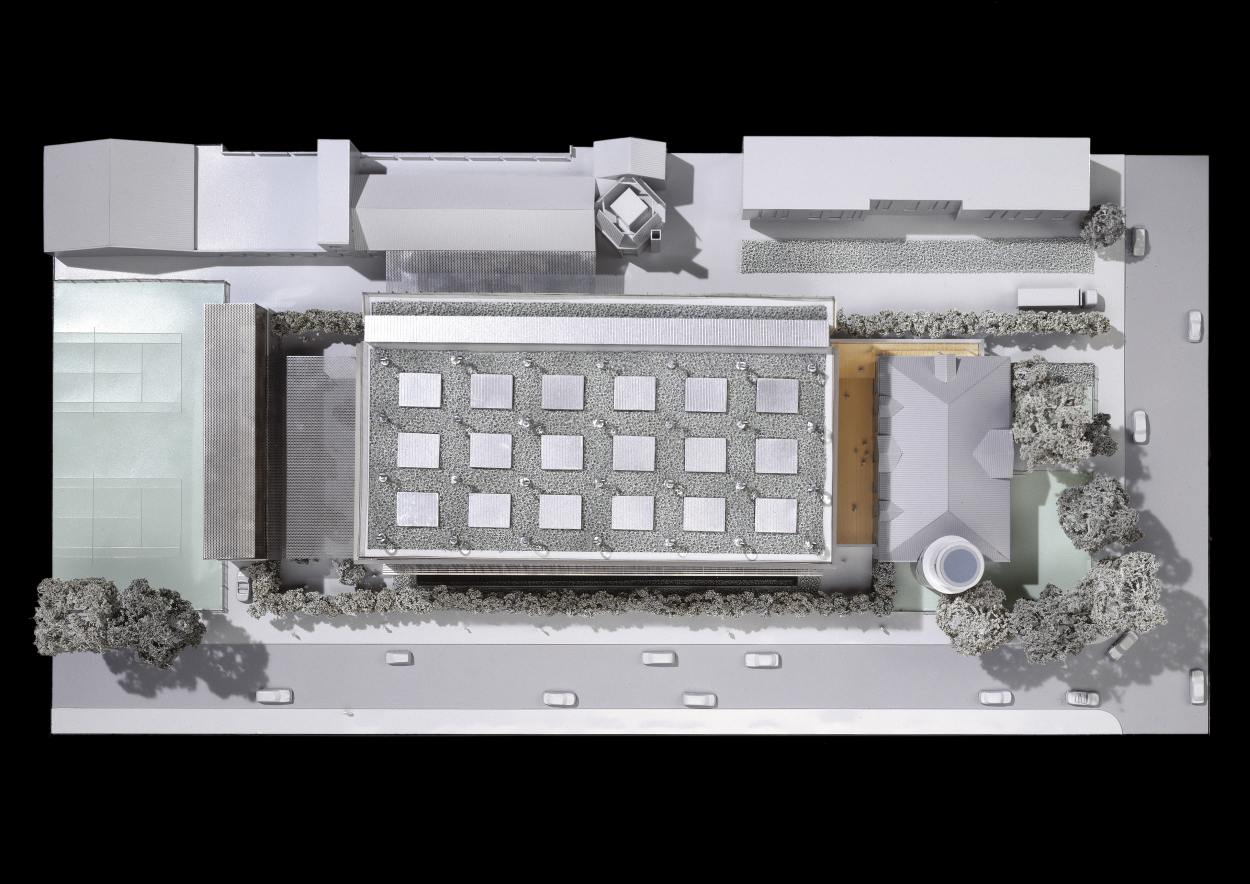
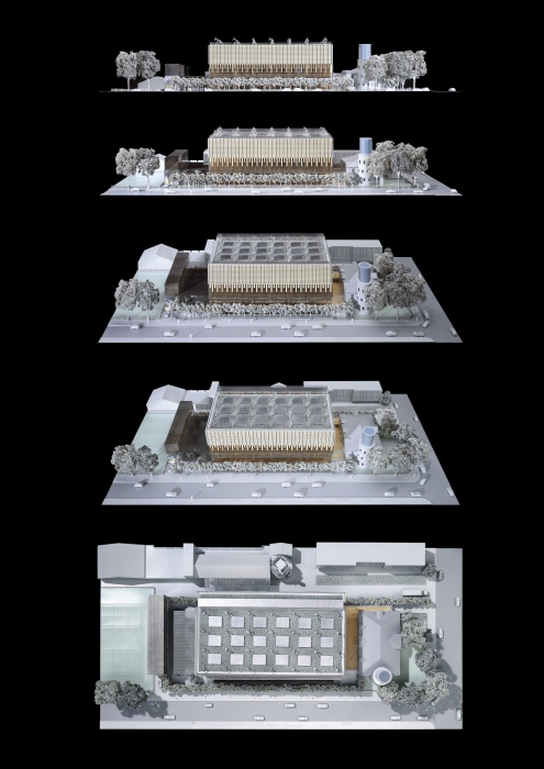
· The planted roof is dotted with 18 skylights (3×6 and covered with photovoltaic cells) that provide zenith lighting for the top level. Twenty-eight (4×7) daylight concentrators are placed directly above the main supporting columns of the building and provide light. In addition to their role in the energy design of the project and in particular of the hybrid lighting system, this field of “sunflowers” follows the trajectory of the sun, and may perhaps, with time, become the very symbol of the building.
· The “strip” of glazed, vertical circulation extends onto the roof and provides access to a walkway along the perimeter of the roof, thus providing views of the city, and allowing a close-up view of the daylight concentrators.
· The façades (SOUTH, WEST and NORTH) of the building (containing services) are clad in weathering steel, of a rust colour similar to the wooden panels. The base of the latter is underlined by green planting, thus visually reinforcing the WESTERN alignment of the site.
· The glazed envelope of the atrium is supported by a stainless steel frame (with double thermal cut-off capacity), and equipped with motorised exterior blinds, from a height of 2 metres onwards.
· The entrance to the garage and the children’s platform features a cladding of grey stone, similar to that of the former meteorological Observatory.
4. General construction principles
The construction is theoretically designed as demountable. Its materials should generate the lowest production of CO2 and energy possible (intrinsically, and with a minimum amount of embedded energy spent in fabrication, transport, and assembly).
Preference is given to the use of wood (in sections and multi-foil panels), stone (in quarry stones and slabs) and steel in diverse forms.
Unnecessary glazed surfaces are avoided. The use of reinforced concrete (with low contained energy, but high production of CO2, non-demountable and recyclable) and aluminium (with very high embedded energy, including for recycling) or plasterboard (non-recyclable) are, for example, avoided or used to a strict minimum.
5. Structure
Infrastructure
The level of the water-table is assumed to be more than 8 metres below the level of the ground. The walls against the earth can therefore be made from gabions and sheet pile (non-waterproof), shored up at each level, and the driving surface on the second basement level will be a bitumen screed on a stone base. The ground is assumed to be friable, compacted by vibrated gravel shafts to form the bases for the columns and gabions.
A planted area lines the EAST walls on the second basement level and is lit with daylight coming through the glass walls of the ground floor. Drainage for the planted areas will be natural and insulated from the run-off water from the garage, which will be treated separately before being discharged into the sewers.
Responsible recycling is envisioned for all site related material.
Superstructure
The main building is made up of two separate structures:
· the first structure houses the exhibition areas on three levels above the ground (each 7.2 metres high), including two basement levels; (respectively 4.5 m and 4.7 m high). This structure is part of a rectangle 59.4 m long and 27 m wide. The solid wood floors rest on a group of 28 columns forming a rectangular grid measuring 9 m x 7.5 m, creating overhangs of 2.25 m on the long sides and 2.7 m on the short sides (6 bays measuring 9 m and two overhangs of 2.7 m, three bays measuring 7.5 m and two overhangs of 2.25 m). The columns are also made from solid wood hollowed out, with a cross-section with an exterior diameter of 90 cm and interior of 30 cm.
The floors have an overall thickness of 1.2 m, including a continuous upper slab in wood measuring 22.5 cm on cross-beams of 1.2 m in total height and 37.5 cm wide. These beams have check-outs at regular intervals to allow for the ventilation shafts (the largest of which has a cross-section of 40 cm x 80 cm), as well as smaller pipe-work for liquids (including the sprinkler system), electrical cables and fibre optics.
A suspended ceiling, load bearing, in wooden panels 15 cm thick encloses the caisson for the floors.
Fire-resistant inspection hatches are spread at regular intervals throughout the floor and ceiling to provide access to equipment.
· The second structure houses the service area along the west side of the exhibition area at 3.6 m and the same height as the display area; it has an overall width of 4.2 m and is 60.6 m long. This structure is made entirely from steel and wood and has six levels.
6. Interior fittings
The intention is, subject to the recommendations from the future museographical study, to regroup areas and themes in the exhibition zones by means of oversize textile envelopes. The flexibility and tactile nature of these fabric walls is meant to complement the regularity and rigour of the main structure.
The fabric itself could eventually graphically express the socio-cultural aspirations and the scientific and technical research displayed within. This fluid and supple layout is suggested on the ground floor, while a more angular, orthogonal layout is proposed for the first and second floor display areas.
In order to contribute to the overall flexibility wished for the ground floor exhibition area, it is suggested that the very walls of its unusual auditorium be composed of sand bags, thus creating an over scale patchwork easily identifiable to the general public.
7. Technical
Particular attention must be paid to all of the technical spaces in the building, especially for the production of heat and cold, by using state-of-the-art renewable energy technologies (such as storing energy in the earth, adiabatic cooling, etc.). One very special and essential feature of the project is the hybrid lighting system. The light sources currently available for the artificial lighting of the exhibition rooms and for the highly specific museological requirements, consume a great deal of energy.
We have therefore decided to use natural light in the most efficient manner possible, without adversely affecting the museological requirements. We will do this by placing 28 diffuse light-concentrating domes at the top of each hollow column. A bundle of fibre optics is connected to each of the domes, descending like the marrow in a bone, through the centre of the wooden columns, and distributed to each floor and thereafter among the fibre optic spotlights of the various exhibition rooms; this means that the cross-section will become smaller from the top to the bottom.
An electric light generator above each column and in the ceiling of the second basement level is linked to a second bundle of fibre optics with a cross-section that becomes smaller from bottom to top, also distributed to each floor and spotlight.
A consistent level of lighting can therefore be assured by the electric light provided by the ascending bundle in the event of there being insufficient light supplied by the descending bundle.
Document E41_01/477 -En Issue of 2005-07-11
01-477 Museum and communication centre, Toronto (Ca).
Client: POLARIS FOUNDATION.
Architecture: Associates : J.-P. Buse, B. Debacker, S. Konincks, P.-L. Limbourg, D. Mélotte, S. Pieters, Th. Vandeweyer, K. Verkaik, Th. Wynen.
Associates in charge of the model: Th. Van de Casteele, Th. Vandeweyer (later founder of Make +, www.makeplus.be)
Andrés Fernandez


For plans sections and elevations, please refer to the archives section of the site available from the “references” menu.