282-Thames Path Bridge
Bloomers Hole
Lechlade
UNITED KINGDOM
(1992); (01-282).
Invited competition entry; preliminary design
– Architecture
2000.11.30
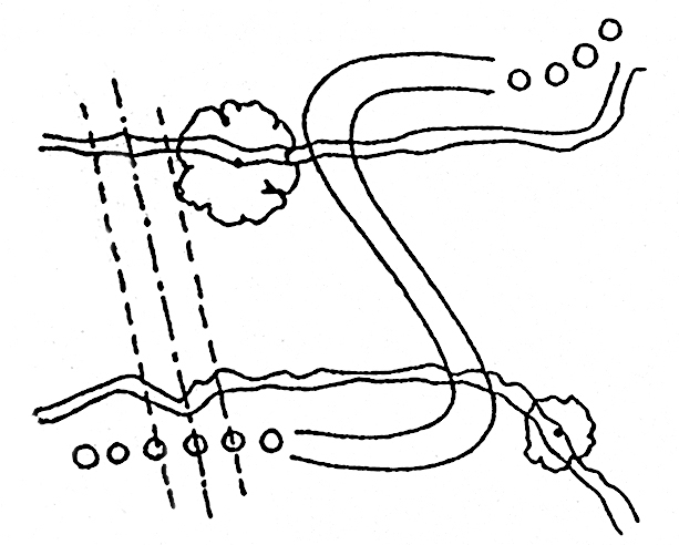
The 10 % slope limit, the necessary height of 3,5m at mid river for boat traffic, and the pipe line restriction, impose a long curved centreline development for the bridge approaches.
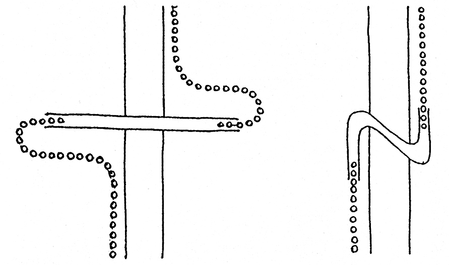
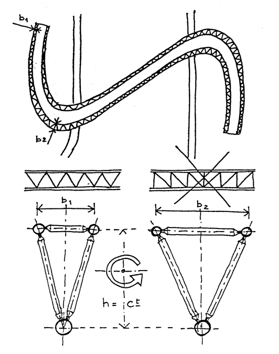
In any case, the track should be close to the bank to avoid unnecessary detours and excessive land use. This implies an overall Z shape.
The structure should be within the parapet height to limit the length of the bridge approaches, this reduces the visual impact and increases the slenderness of the bridge.
The bad soil conditions implies the use of a light structure.
The difficult access to the site implies prefabrication.
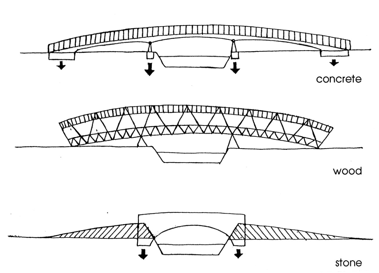
Stone and concrete are thus inappropriate. Wood is feasible for a straight crossing but, to provide longevity, it might need to be protected by some kind of roof which increases the cost and makes the structure too imposing.
This leaves steel, which allows:
– a very light structure which is easy to construct in parts, which are assembled on site;
– a “transparent” structure within the parapet allowing sympathetic visual contact with the river and a discrete presence in the environment;
– an airy structure to be used for the approaches, thus eliminating the use of earth mounds;
– a streaming line for the path as triangular truss beams take torsion forces easily. Pedestrians walk following fluid lines, not lines at straight angles;
– a natural widening of the deck in the curve.
As painting is an important issue for an outside steel structure, it is to be decided in accordance with the Department of Transports Specifications for Highway Works, Samyn and Partners recommending white to increase visual hightness.
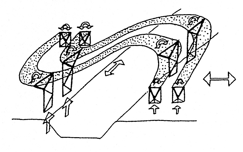
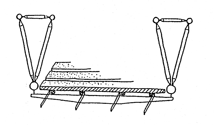
The bridge consists thus of two truss beams with a variable triangular cross section; the beam height being constant, only its upper width varies to cope with the torsion moments. The truss is of the WARREN type which is lighter than the PRATT or HOWE configuration.
The beams follow the sweeping line of the path and are supported on four points which present torsional stiffness.
The supports are arranged in such a way to absorb the lateral forces and wind load, and to allow free expansion under thermal load. All the members of the beams are tubular, with tapered ends, for the sake of low maintenace cost and structural efficiency. The two curved truss beams, each composed of four elements bolted together on site, are easily transported on two 15 m long trucks and on roads with a normal 4,5 m height clearance.
The transversal beams of the deck are “hung” from the bottom chords of the trusses by means of workshop welded rectangular plates.
The transversal beams are tapered IPE 120 to 160 depending on their span of 2 to 3 meters.
Four longitudinal plates 10 mm x 60 mm are workshop welded on the IPE’s, and serve as support for the thick oak planking which forms the walking deck and has open joints to allow for simple drainage.
The deck is made of tree standing panels resting on rubber strips on the IPE’s to avoid punching and wearing of the paint on the steel.
The slip resistance of the decking must be in agreement with the Technical Approval Authority.
The bridge supports rest on piles of a 500 mm diameter which are bored and cast in situ, because the ground is not suitable for direct bearing, particulary for a continuous structure that is sensitive to settlement.
These piles may require temporary casing for about 5 m to allow for poor ground conditions near the surface, and present an overall length of 9 m, though it must be confirmed at Detall Design Stage.
Pretensioned cables complete the truss to form the parapet and are in stainless steel with tension turnbuckles regularly spaced.
They glide in PTFE gaskets located in small steel rings shop welded to the structures tubes in the workshop.
| 01-282 | THAMES PATH BRIDGE COMPETITION, GREAT-BRITAIN. |
| Client: | THE COUNTRYSIDE COMMISSION. |
| Architecture: | Gh. André, J.L. Capron, J. Ceyssens, A. Charon, Ch. Fontaine, A. O’hare, R. Tapia, V. Van Dyck with MOUCHEL engineering. |
For plans sections and elevations, please refer to the archives section of the site available from the “references” menu.


