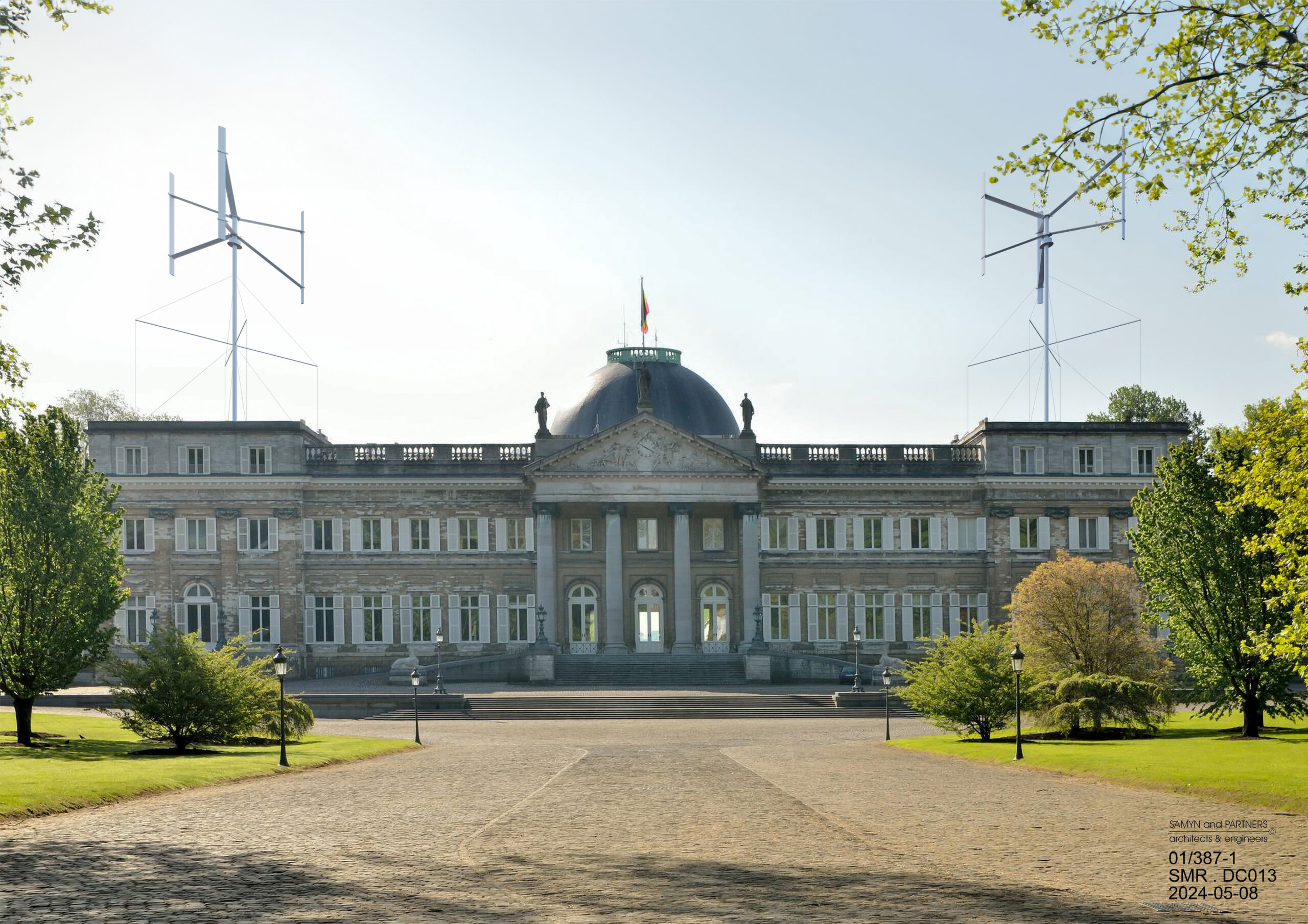
01/387-1 – Darrieus H-Rotor wind turbine with retractable shrouds
In development for FAIRWIND (Fleurus – BE)
BELGIUM (2024 – ); (01/387-1).
The demand for small quantities of electrical energy for isolated buildings has led to the development of “micro-wind turbines” since the 2010s. These turbines, with a power output of P ≤ 50 kW, are often of the Darrieus H-Rotor type, characterized by a vertical axis of rotation.
A mast with braced stays, made entirely of steel, allows for a fully demountable structure without the need for concrete and with an extremely small environmental footprint. Including the foundations, this design is by an order of magnitude lighter than a self-supporting tubular mast, requiring ten times less embodied energy. Consequently, it can also be installed on the roof of a building.
Dynamic loads on the structure can be mitigated using viscous dampers in the cables and by filling the mast with sand. This approach provides both dry friction damping (Coulomb damping) and enhances the elastic stability of the mast’s thin walls.
The system can be precisely installed and further adjusted as needed.
Assembly components:
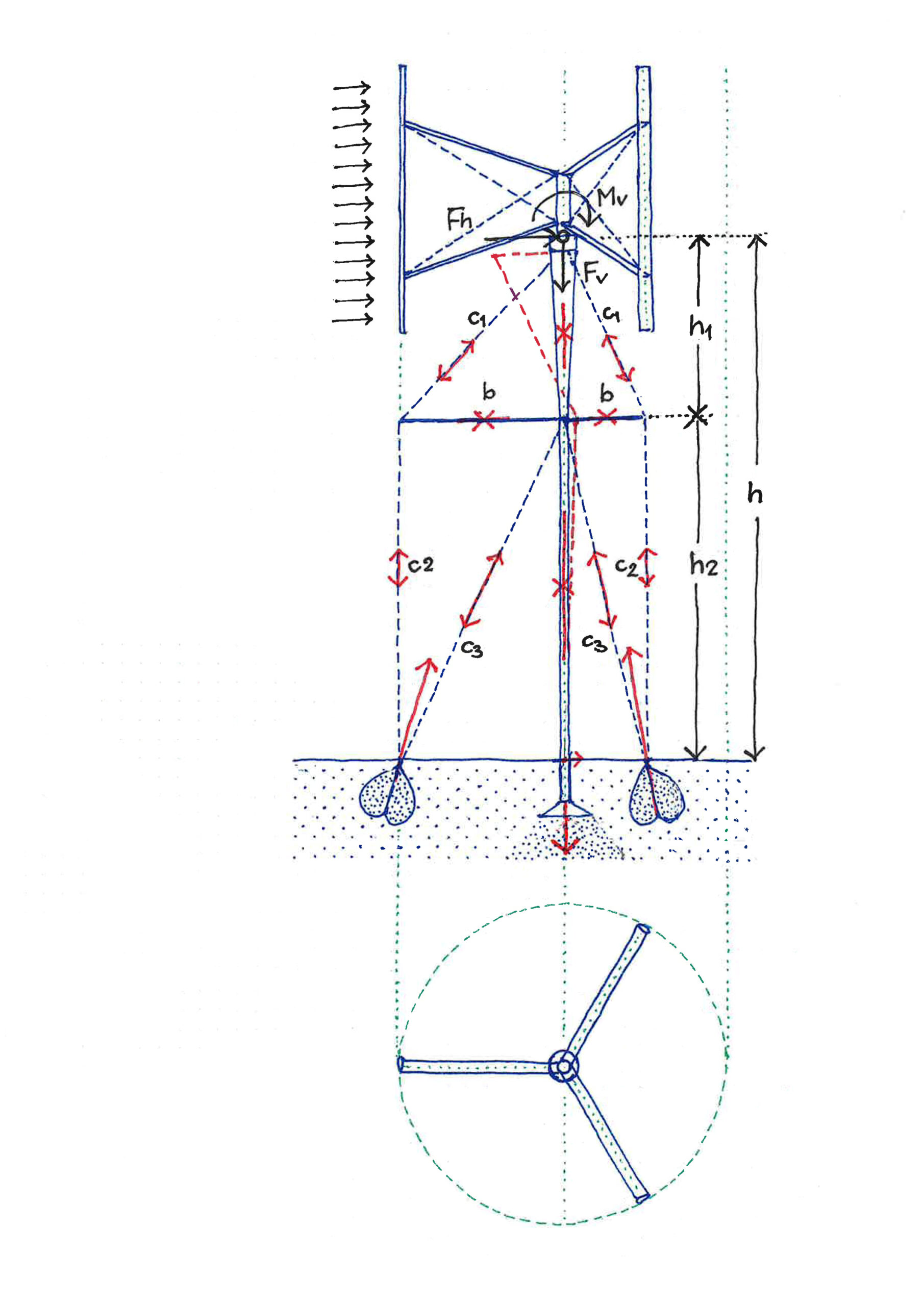
• The mast, of height h under the rotor, consists of:
– An upper section shaped as a truncated cone with height h1≈h/3.
– A lower cylindrical section of height h2≈2h/3, filled with sand.
• The mast is subjected to:
– Horizontal wind forces Fh at the top of h1.
– The rotor’s weight Fv.
– A small torsional moment during braking.
– Wind-induced torque Mv , which reduces to approximately Mv/10 at the junction of h1 and h2, and then to zero at the base of h2.
• A truncated conical sheet metal foundation at the base or a vertical support on a building structure.
• Three (or four) compressed horizontal struts (b) arranged in a star (or cross) configuration at the junction of h1 and h2. These struts are as long as the rotor’s radius of rotation (measured from the assembly axis).
• Three sets (c1, c2, c3) of three (or four) tie rods (bars or cables), potentially fitted with viscous dampers:
– c1: Connects the top of h1 to each end of the struts at an angle, transmitting force Fh and applying additional compression to h1.
– c2: Vertically connects each strut end to ground anchors or to bracing columns/walls on a building, balancing forces in the struts and c1 rods.
– c3: Connects the mast at height h2 to the anchors, transmitting Fh and applying a second additional compression force to h2.
• Three (or four) anchor weights, which can be:
– Nets shaped like a section of a cardioid, pulled by a cone and filled with ballast.
– Anchors in a rock substrate.
– Anchors connected to the building structure.
Architecture and Engineering: Philippe SAMYN and PARTNERS All projects are designed by Philippe Samyn who also supervises every drawing