575-Footbridges over the canal and motorway
Ghent
BELGIUM
(2010); (01-575).
Invited competition entry
– Architecture
– Civil engineering
– Cost control
– Landscaping
– Masterplan
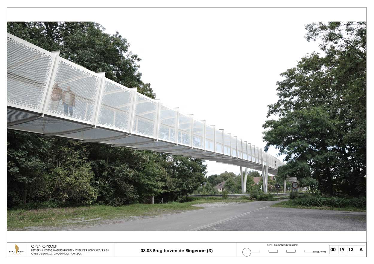
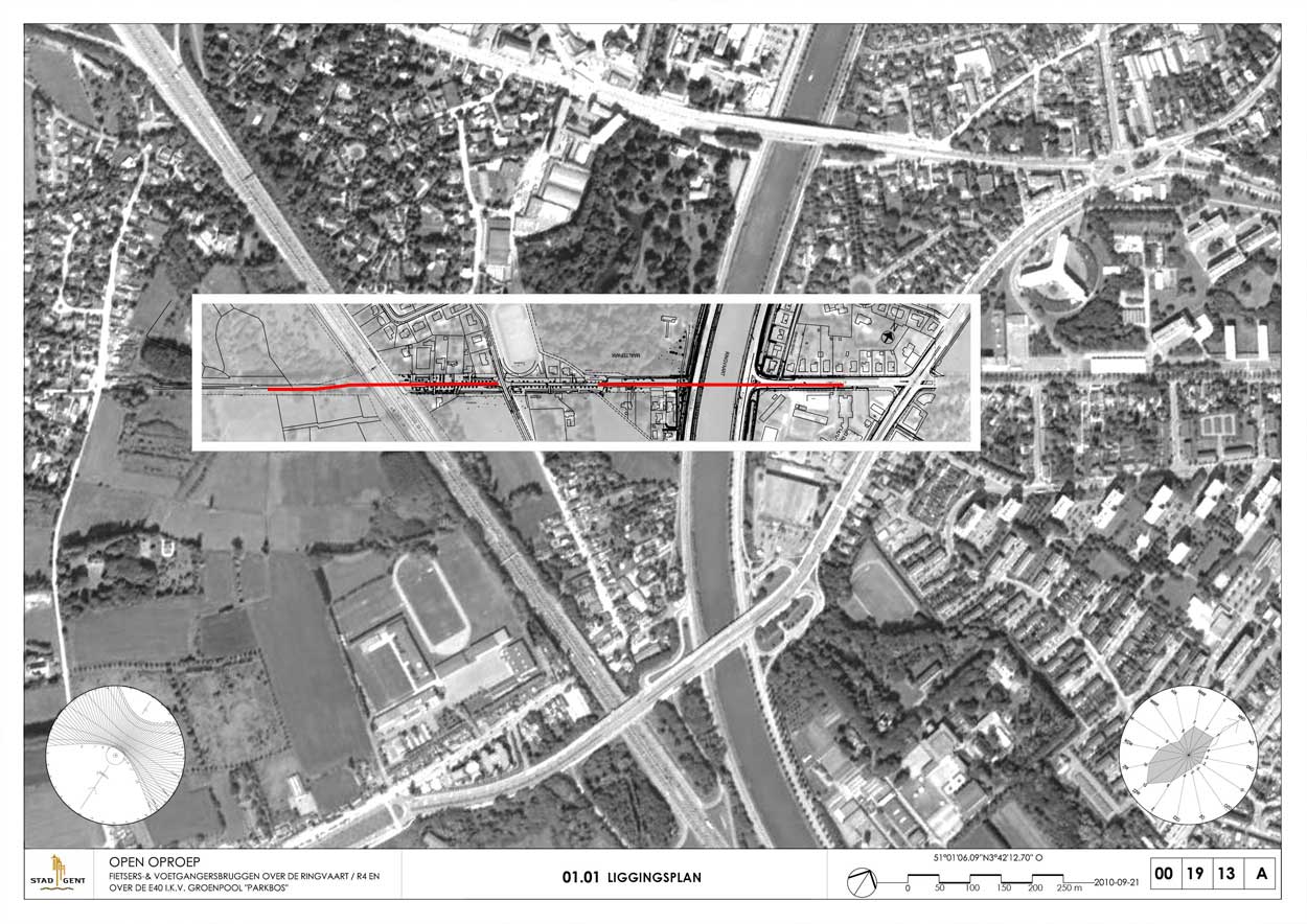
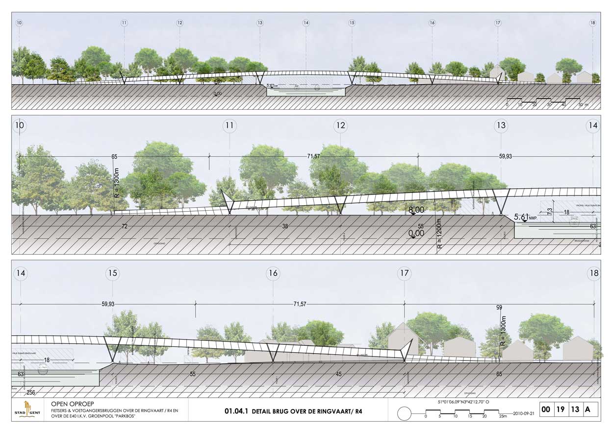
The two footbridges, intended for pedestrians and cyclists, are located on the site of a disused railway line and link the outskirts of Ghent with the city itself. They cross the canal (or the Ringvaart) and the E40 motorway successively. Given the slight incline of the paths, each one will be 266 m long.
The following criteria determined the design of the two footbridges:
- low live loads (the bridges can therefore have a lightweight structure so long as it is offset by stiffness);
- limited elastic deformation;
- reduced wind load
- protection of users against wind and rain;
- views over the surrounding landscape;
- walls preventing the risk of persons or objects falling;
- smooth surfaces with no sharp edges;
- non-slip treatment of the horizontal surface;
- rapid water drainage;
- easy access for safety and security services;
- low-cost assembly with little environmental impact.
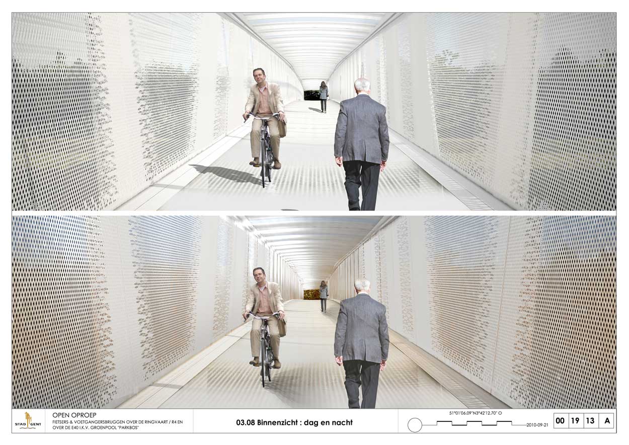
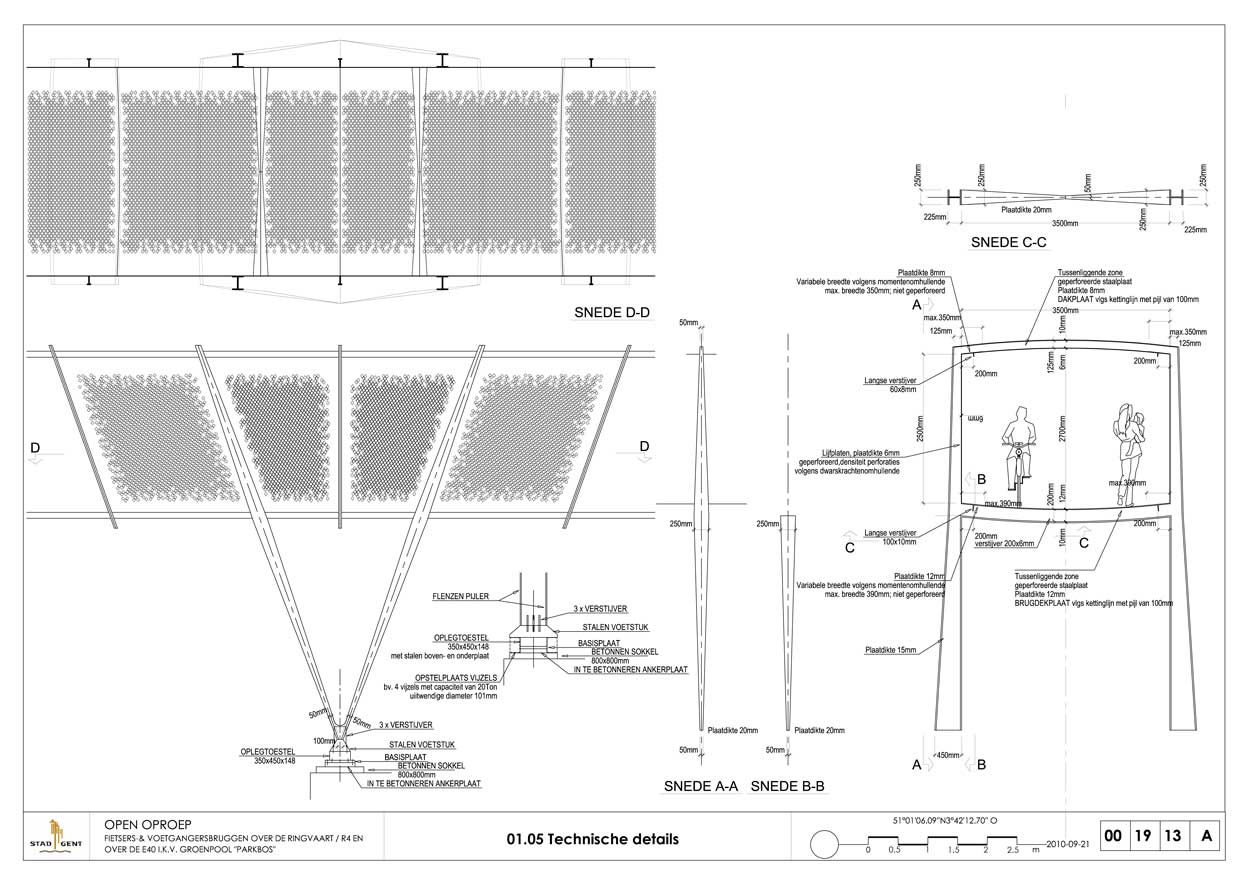
The footbridge will take the form of a “transparent” steel tube with a waterproof constant-section roof, made of perforated metal, stiffened by regularly placed exterior frames. Its longwise appearance will be studied to keep inclines to a minimum.
There are several reasons for using perforated metal sheets:
- they offer smooth, continuous surfaces with no need for handrails,
- they enhance user comfort by reducing wind speed,
- transparent fluorinated film on the outside of the roof sheets provides protection from the rain,
- and finally, the perforated floor prevents any build-up of water or ice.
The floor and roof of the bridge section come in cylindrical segments, with the generating line in the form of a catenary curve. This arrangement keeps the amount of material needed for the floor to a strict minimum and guarantees effective drainage of rainwater from the roof.
The perforations disappear on the vertical walls at the place of the stiffeners, on a width that vary depending on the distribution of bending moments. A 50 mm-high stiffener, set back slightly, follows the same line and supports the artificial lighting.
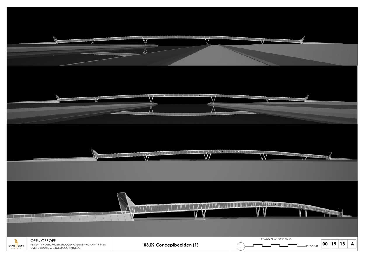
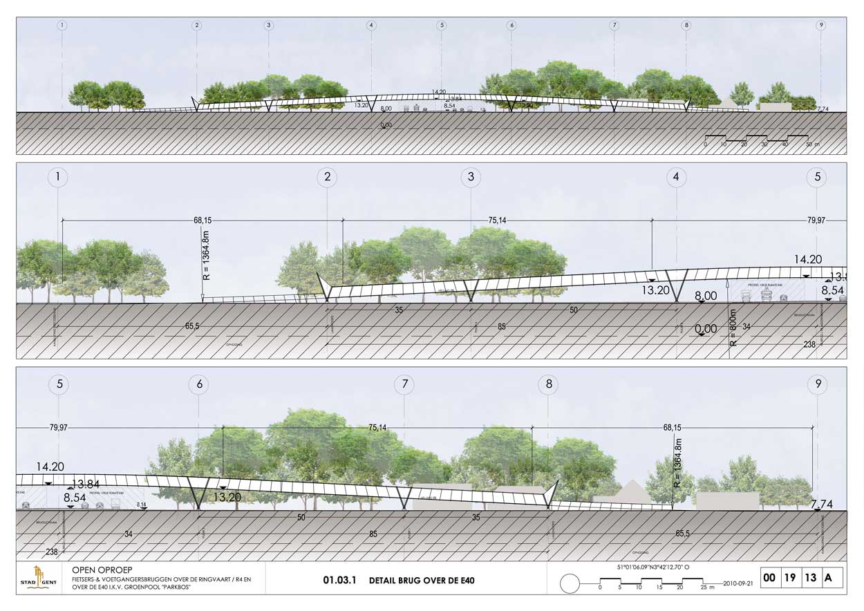
The overall dimensions of the floor are therefore kept to a strict minimum, ensuring the deck has a descending gradient that is as slight as possible (on average 4 %).
Furthermore, the tubular section allows easy take-up of torsion stress caused by the S-shaped distortion in the bridge’s alignment where it meets Oudespoorweg.
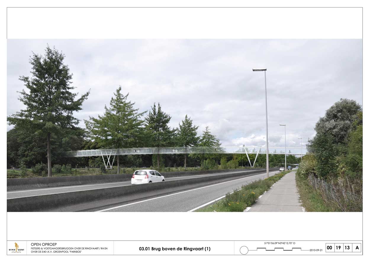
To avoid risks of accident, the supports are positioned away from the motorways, particularly on either side of the Ringvaart. They are in a “V” formation to enable perpendicular connections on either side of the Ringvaart. This means a shear-resistant framework must be envisaged.
The footbridge is divided into segments no more than 68 m long, welded together in a workshop and delivered by boat. They are placed on the supports in a V-shape and welded to one another one by one. No additional expansion joints are used, other than those at the far ends of each bridge.
The central spans were swung into place over both the Ringvaart and the motorway. The end sections of the bridge on the motorway were rolled from the edge of the Ringvaart over sections already in place.
The benefits of tubes with membrane walls, where the stiffened frames rely on post-buckling strength, have been familiar since the work of Lynn Beadle in the 1960s (Lehigh University, Pennsylvania). This concept very quickly came to be used in heavy goods trailers made of high-strength steel or aluminum.
The project to build a sheet metal footbridge was conceived several decades ago but to date had always encountered numerous practical obstacles.
In the last 20 years, there has been rapid and continuous development of several key aspects of metal construction technology:
- the availability of very high resistance steel plates (in particular as a result of scientific, industrial and technological work at Sidmar),
- continuous performance improvements, as well as reductions in the cost of on-site welding and complete mastery of quality control,
- increasing sophistication of industrial tools, particularly with robotized cutting and assembly at metal designers,
- finally, the development of new calculation software and the Eurocodes has enabled very high-precision calculations.
Thus, the concept of a membranous tube bridge is now feasible in a way that is particularly cost-effective and efficient. To the designer’s knowledge, the tubular structure proposed here is the first of its kind.
The extremities of the bridge, as well as the four intermediary support points – which are very stiff points in the overall shape and prone to significant movement – are therefore ideal to take on the shock absorbers that may be required following the detailed dynamic study.
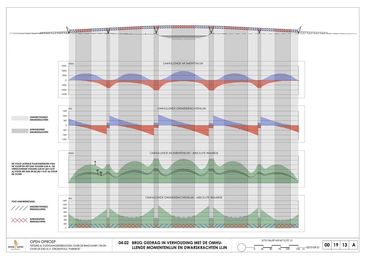
Distribution diagrams of bending moments shows that, in all loading events, there is a variation of only 40 % in moments along the total length of the structure (with the exception of the extremity supports where they cancel one other out).
The same is true, although at a slightly lower level, of the shear force, which varies only in the ratio of one to two, with higher values in the areas (near to the supports) where the forces remain the same and lower values in the areas where the forces alternate (in the span).
These remarkable characteristics confirm the merits of constant-section tubes with little variation in the amount of material along their length. They also show the benefits of V-shaped supports which strongly reduce peak stress on the supports.
Cover plates for access to the roof are planned in areas where bending is weakest – approximately every 50 m. The central section of the roof actually has no significant impact on the bridge’s bending strength and yet it is essential in terms of torsion resistance and stiffness as well as dynamic stability.
Integration into the landscape raises the issues of form and slenderness.
Keeping the height of the structure to a strict minimum in the interests of anorexic slenderness is only too common an approach to footbridges. These slimmed-down structures can, in extreme cases, appear simply weighed down by railings and other devices necessary for safety and comfort.
The opposite is true here with an ample yet highly transparent structure which keeps weight to a minimum and allows for an enjoyable crossing. It is this very real transparency that justifies its presence in the landscape: it resembles a light and generous Niki de Saint Phalle balloon rather than Giocometti’s hefty slivers.
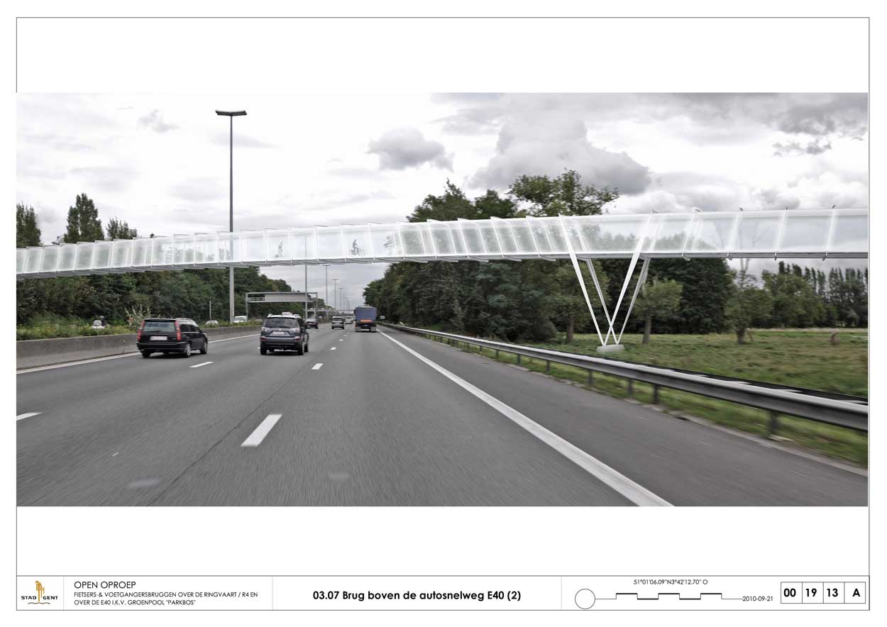
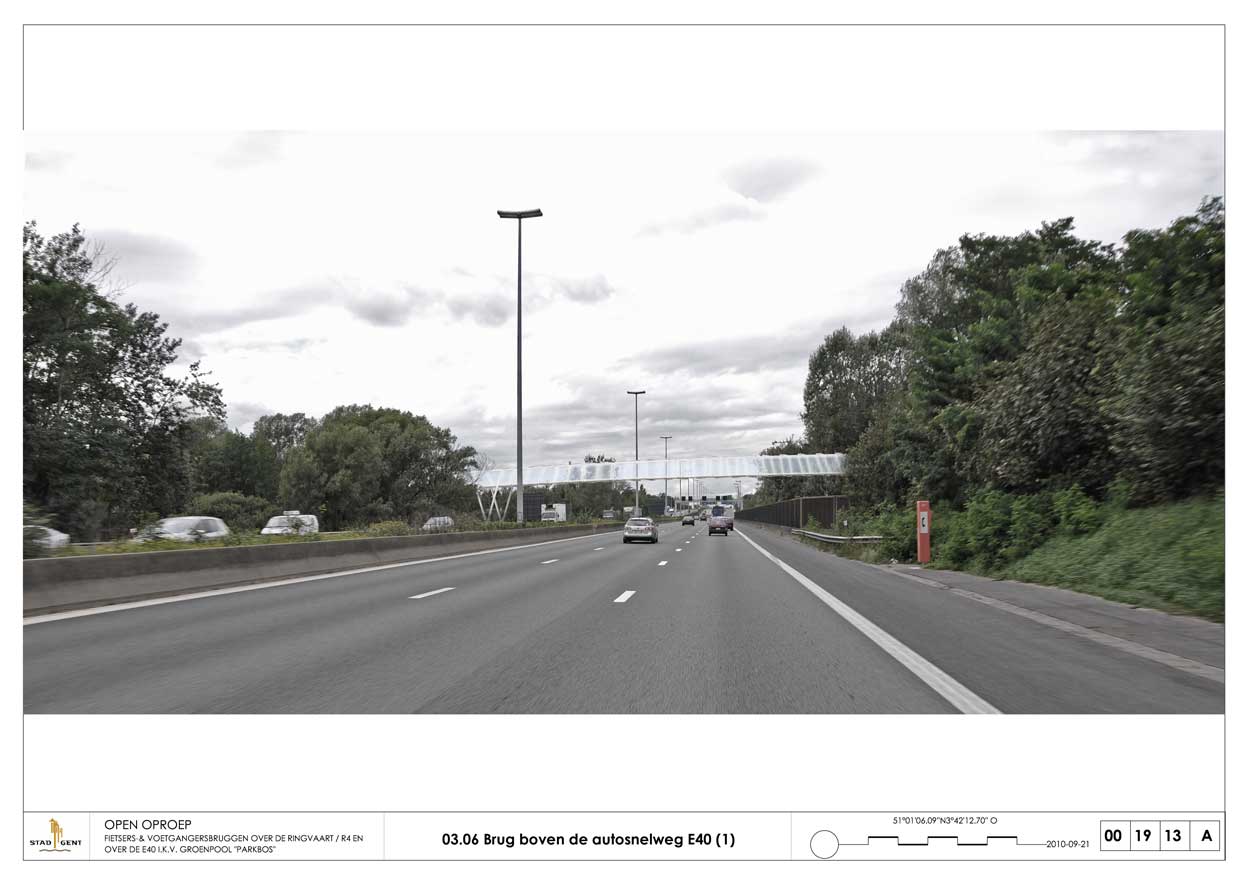
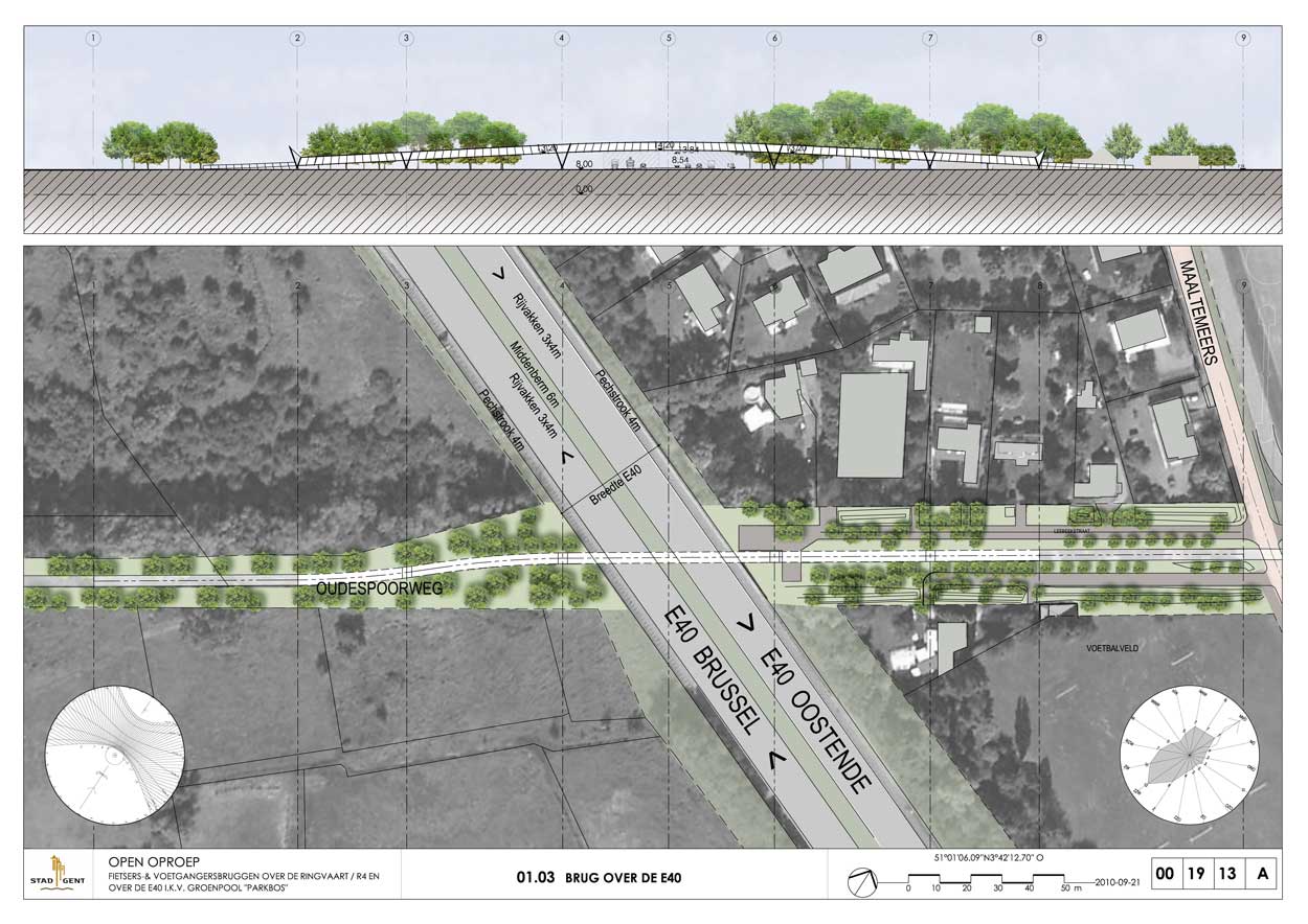
Without exaggeration, its presence in the landscape is evident but discrete. Above the motorway, the footbridge is at a constant height and could be visually compared to the frames that carry road user information boards and, moreover, could be used as such.
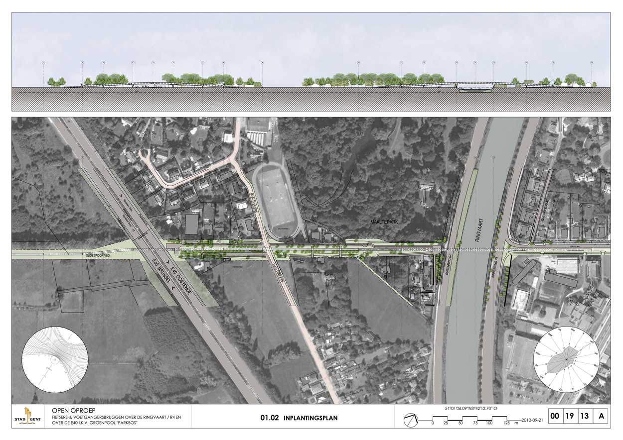
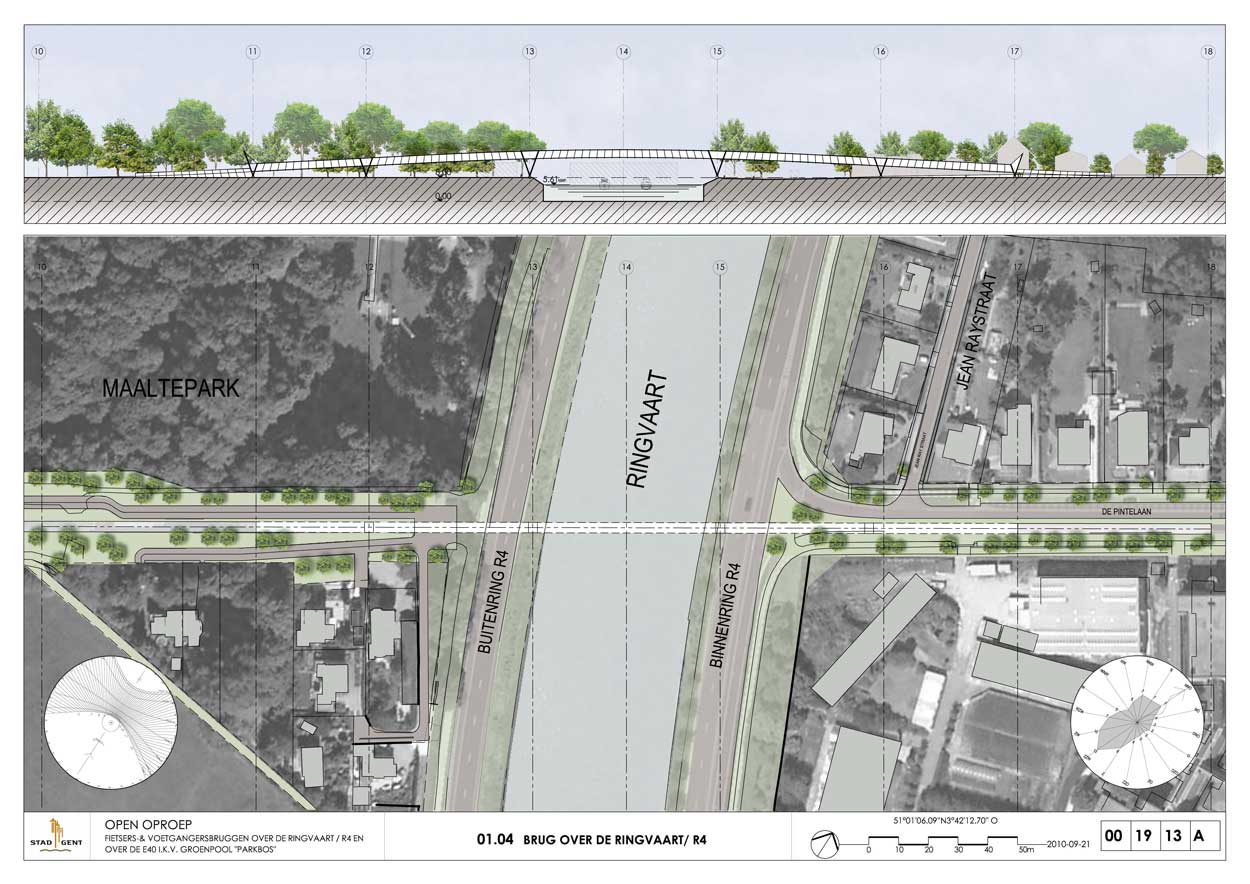
The structuring character of the footbridges in the landscape requires that they be built along the axis of the tree-lined Leebeekstraat. The bridge therefore begins south of De Pintelaan, crosses the Ringvaart and the motorway in a straight line and then forms an S-shaped distortion on the edge of Oudespoorweg.
This layout means the majority of Leebeekstraat’s trees will survive.
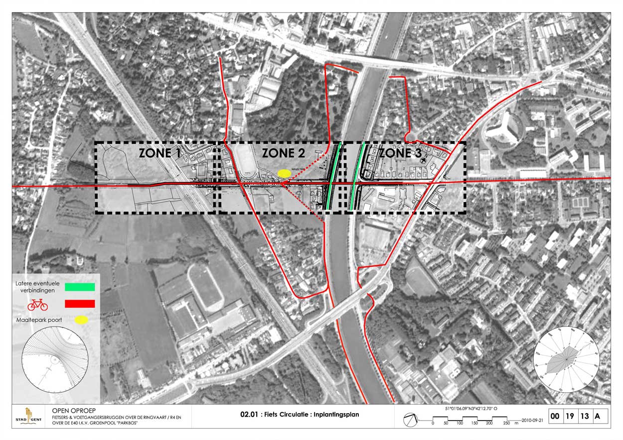
Houses to the eastern side of this road can be accessed via a new path to the north, which also leads to the Maaltepark. Two paths flanking the footbridge enable transit between the motorway and the Maaltemeers. All these paths thread their way between existing trees and the majority of the existing ditches survive.
The approach spans, in the form of earth berms, are equipped with 1 metre-high perforated and stiffened metal balustrades in the style of the footbridge itself. On the Oudespoorweg side, the ground is water-permeable.
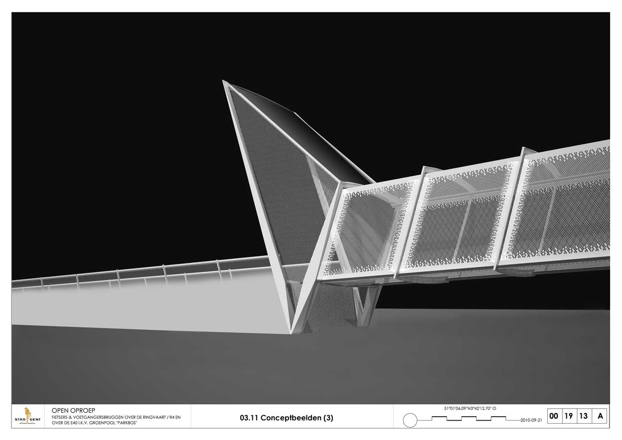
Particular care has been taken over the form of the footbridge entrances, where the bridge, the ground and the sky come together. Vast prismatic steel collars “embrace” the footbridge entrances in welcome. It is also set with large polished stainless steel mirrors.
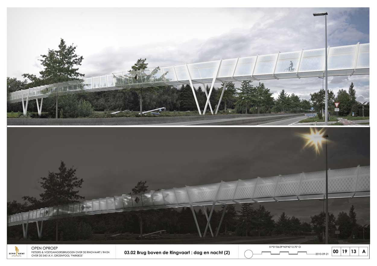
Apart from the mirrors at the entrance, the entire bridge is made of white-painted steel.
White was chosen partly because it allows the structure to blend into the landscape and also because it gives the inside of the bridge a luminous intimate atmosphere (where glare and clashes of light are avoided).
The slip-resistant ground surface is formed from an epoxy resin between 1.5 and 2 mm thick, peppered with quartz grains in the workshop.
The bridge is lit by 1 m-long LED striplights, installed on one side of the bridge – one on each piece of structural mesh.
Philippe SAMYN and PARTNERS All projects are designed by Philippe Samyn who also supervises every drawing
Structural Engineering:
Philippe SAMYN and PARTNERS with SETESCO (sister company 1986-2006) or INGENIEURSBUREAU MEIJER (sister company 2007-2015) if not mentioned
Philippe SAMYN and PARTNERS
with FTI (sister company since 1989)
if not mentioned
| 01-575 |
TWO PEDESTRIAN BRIDGES, GHENT. |
|---|---|
| Client: | CITY OF GENT. |
| Architecture: | Partner in charge : J. Ceyssens. Associates : L. Barbarito, Th. Cooreman, F. Defrenne, R. Gijbels, D. Gundes, O. Jottard, C. Lizin, Th. Naessens, S. Tourbach, S. Van Der Meer. |
Document E41_01/575 -En Issue of 2011-11-15


For plans sections and elevations, please refer to the archives section of the site available from the “references” menu.