
Page 208 - THE FIRE STATION
P. 208
206
Focus area 4: Innovation and development of reflection and its mechanical properties, and the way it fits
During the competition phase, the design team proposed a system in with the building’s architecture. The rings of the primary he-
allowing natural light to be channelled towards the building’s main liostat allow a rotation on two axes at a high level of precision
staff entrance on Level 0. (<1%) via an automatic tracking system. A display is planned
in the technical control room allowing parameters to be visu-
The idea is based on a simple finding: Only very little direct sunlight alised online. Apart from the mechanical optimisation achiev-
reaches the depths of the central atrium, while Level 0 gets no sun- ing a lightweight and long-lasting structure, solar studies were
light at all throughout the year.The challenge was thus to come up conducted to check the optimal functioning of the whole system
with a system overcoming this shortcoming. [Fig. 10] (study of the shading, determination of the level of precision
needed for tracking, position of the sun in real-time, theoretical
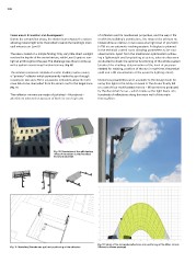
The solution proposed consists of a solar tracking system using yield and a 3D visualisation of the system’s lighting effect).
a “primary” reflector which permanently tracks the sun through
rotating on two axes.Three successive reflections allow the lumi- Numerous possibilities were available to the design team for
nous halo to be channelled from the atrium roof to the target zone. using this light in the lobby on Level 0. The choice finally fell
on a set of four multifaceted mirrors – Miros mirrors produced
[Fig. 11] by the Zumtobel Group – which break up the light beam into
hundreds of reflections along the main wall of this main
The reflector mirrors are made of polished – Alucobond – thoroughfare.
aluminium selected on account of both its very high rate
Fig. 10: Simulation of the self-shading
effect of the atrium (using Autodesk
Ecotect Analysis©).
Fig. 11: Modelling (Bemelmans sprl) and positioning of the reflectors. Fig. 12: Study of the successive reflections and positioning of the Miros mirrors
(Dialux© software package).