
Page 215 - THE FIRE STATION
P. 215
213
TECHNICAL SYSTEMS
Andrew Janssens
SITE PREPARATION
The site of the new Charleroi fire station is on the south-east flank vides water for the inside and outside fire hydrants.The manhole
of the Hiercheuse slag heap. Set back from the road, it is accessible containing the underground meter is alongside the one for the gas
via the Sentier desTerrils from the Rue de laTombe with its public meter and the feed pipes follow the same routes a the other mains.
utility networks – indispensable for providing mains services –,
which have been extended specially for the new fire station.The Water draining off the roofs and roads is channelled into a separate
underground mains connecting up the building follow the road and sewer at two points along the Sentier desTerrils. Some 35% of this
link up to a series of technical rooms located along the basement water flows into the main sewer on the west of the site under the
pedestrian access path. road used by emergency vehicles, while the rest is discharged to
the south, below the site.The urban rainwater sewer network chan-
The building is connected to the utility company’s medium-voltage nels water to a retention basin located on the south-east of the site
(11,000V) electricity network. Its meter is placed in an outdoor bordering Rue de laTombe.
hut on the site’s perimeter.The cable feeds into a very low loss
(A0Ak) transformer located in a room of its own in the fire station’s Rainwater from the fire station’s main roof is collected in a 100m³
basement. Interconnected draw-in boxes are located along the reservoir made up of 5 prefabricated concrete cisterns buried in
underground cable duct, allowing further cables to be drawn in and the grounds to the east of the building. Water passes through an
connected to the mains network at a later date. upstream sediment filter before entering the row of cisterns, the
last of which has an overflow connected to the sewer system.
The building’s central heating system, located in the basement, Rainwater is used for flushing toilets and urinals, as well as for
runs on town gas fed in through an underground pipe via the utility washing emergency vehicles and in the upkeep of the patios,
company’s meter located near to the electricity hut.The gas pipe terraces and the surrounding beds.
enters the building in a room (also used for the drinking water feed
pipe) meeting the requirements of ATEX 1 rooms. Fuel supply can The water flowing off the vehicle manoeuvring area next to the
be cut off here in the case of a gas leak being detected in the central training tower to the north of the building is collected in a 20m³
heating system. underground concrete tank, again with an overflow connected to the
sewer.This tank is linked to a fire hydrant and serves as a source of
Twin underground feed pipes link the fire station to the water net- water when practising putting out vehicle fires or fighting hydrocar-
work, also via the utility company’s meter.The first pipe connects bon fires.The emulsifiers used for extinguishing Class B fires (fat) are
up to the building’s drinking water network, while the second pro biodegradable, allowing them to be discharged into the public sewer.
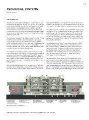
Cross-section between axes 11 and 12.
Positioning of the technical rooms between axes 11 and 12 and the principles behind mains distribution.