Basic HTML Version


87
Although Philippe Samyn sets out to create
structures that are light and made from slender,
low-visibility structural elements, it should be
noted that the structure as a whole is above all a
geometry that is made to be seen; the art of the
architect is to select the right orders of size.
For example, for two elements to appear identical,
a basic rule is that their lengths should not differ by
more than 2 per cent. In the same way, understanding
a structure should be based on easily visible ‘relaying-
subdivisions’, which punctuate the viewer’s visible
perception. For a principle construction element to
remain visible across the facade, it should be no more
than seven times smaller than the facade’s transversal
dimension. The same principle applies to secondary
elements with respect to a main element, and so on, in
much the same tradition as that followed by the build-
ers of cathedrals. In his search for lightweight forms,
Philippe Samyn also became passionately interested
in spatial structures generated by a network of regular
polygons – six equilateral triangles form flat hexagons
(figure 50)
, five equilateral triangles form a pentagonal
dome (curvature in the same direction, elements in
compression), and seven equilateral triangles form
saddle-shaped heptagons (opposing curvatures, ele-
ments in tension), which means that structural rigidity
can be given to stretched canvas. In 1970, Philippe
Samyn developed structures consisting of assemblies
of triangles in order to form a surface of revolution
– isobar structures (isosceles triangles, i.e. with two
sides of identical length) and isonode structures (rep-
etitions of nearly identical triangles, giving a degree
A geometry designed to
be seen and understood
of freedom to the nodes).
24
It was not until 1990,
however, that he began to apply the same principle to
equilateral triangles – folded around their three sides to
infinity they create a homogenous structure, like a ball
of wool or a wickerwork basket
(03-198, figures 49 and
51)
. In these principles, we see both zoomorphic and
biomorphic influences. The appearance of a structure
we assume to be disagreeable, like a railway bridge,
can be made more appealing by working on the form.
In response to a heritage request during the widening
of the ‘Snepbrug’, a railway bridge over the River Leie
in Ghent
(01-436, figures 52)
, Philippe Samyn avoided
the problem of the appearance of the bridge by turning
it into a tunnel going through a grassy embankment.
This is more discreet and pleasant to look at, and the
curve that Samyn has given to it made it possible to
create an accessible pedestrian path for people with
disabilities. A nearby bridge over a road was developed
in the same way
(figure 53)
. Within conventional build-
ings, the structure is generally invisible, but Philippe
Samyn believes that one must be just as attentive as
if it were on show; beams and columns must be given
correct outlines, the architect must consider the size of
the spans and make sure the structure can be disman-
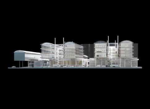
tled. In the project for the Arenberg campus in Leuven
(01-391, figure 54)
, in which the buildings on stilts
resemble a riparian village, everything can be disman-
tled. No element weighs more than a tonne, so that
everything can be assembled and modified without the
use of a crane.
In his own offices, Philippe Samyn has taken care that
the ancillary structures are well proportioned and are in
harmony with the rest
(01-265, figure 55)
: the concrete
beams are flat (wider than they are thick) and placed on
round columns. His search for lightness also led him to
assign a load-bearing role to secondary elements; for
example, the jambs for the frames on the facade of the
crèche in the rue de l’Epée in Brussels
(01-413, figure
56)
play the role of structural columns, supporting that
which is above. Engineers do not deal much with stair-
ways, although they are fine subjects for design. Thus
Figures 52: ’Snepbrug’, Ghent (01-436)
Figure 53: Railway bridge over a road,
Ghent (01-436)
Figure 50: Pentagon, hexagon
and heptagon
Figure 51: Creating a hexagonal
network on a spherical dome (03-198)
Figure 49: Isobar and isonode domes
Figure 54: Project for the Arenberg
campus, Leuven (01-391)
50
49
54
51