Page 149 - AGC_EN_iBook
P. 149
149
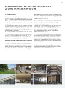
EXPaNSION/CONTRaCTION OF ThE FaCaDE’S LOUVRE-BEaRING STRUCTURE
tHe exPaNSION JOINtS
The glass louvres of the double skin facade are mounted on a steel framework exposed to major temperature variations (-10°C in win- ter, 35°C in summer). The framework is anchored to the concrete skeleton structure, insulated and designed without any expansion joints. Major thermal movements therefore need to be taken into account, with the steel framework and its concrete support react- ing differently.
The IPE 330 pro le on the edge of the roof, from which the whole double skin facade is suspended, has two expansion joints divid- ing it into a central section 17.55 m long (i.e., thirteen 1.35 m mod- ules) and two side sections, each 34.2375 m long (slightly more than twenty- ve 1.35 m modules).
The support structure for the louvres mirrors exactly this division into three sections.
The central section has a xed point at the centre and can expand/ contract by ± 2 mm to the left and to the right.The two side sec- tions similarly have a xed central point, but their maximum expansion/contraction can reach ± 7 mm on each side.
aNCHORING tHe FRameWORk tO tHe BuILDING’S StRuCtuRe
Surrounding the building on every oor, the maintenance walk- ways channel wind pressure on the louvres to the building’s structure by means of the galvanized steel ‘forks’ on which the walkway sections rest. Placed at right angles to the facade every 1.35 m, these forks are xed on their outer ends to the uprights supporting the louvres, and on their inner ends to the building’s
facade by way of small aluminium consoles.Three different types of consoles – called A, B and C, respectively – are foreseen at these points to ensure the free expansion/contraction of all elements making up the double skin facade.
The a anchors correspond to the xed points located in the centre of each of the three sections of the facade, i.e., on each oor:
– two anchors in the centre of the central section (i.e., half a
module on either side of axis 8);
– three anchors in the centre of each of the two side sections (i.e., on the left side, one anchor half a module to the left of axis 3, then – two to the right; and similarly on the right side, one anchor half a module to the left of axis 11, then two to the right).
There are thus 8 xed points for each oor, making a total
of 16 for the whole south facade.
The C anchors correspond to the expansion joints, located half a module to the right of axis 6 and half a module to the right of axis 9. The expansion/contraction of the lips of these joints is ± 7 mm towards the ends of the facade and ± 2 mm towards its centre.
At these points, the walkway is not bolted to the ‘fork’, instead just resting on it, and is held in place by studs on which walkway grat- ings can slide freely.
Finally, B anchors are used for all remaining intermediate supports. Though the ‘fork’ is connected to the walkway, its end has two studs enabling the walkway to slide freely in two holes provided for this purpose in the small aluminium consoles.